9 term definition – JUMO 902931 Wtrans Receiver with Wireless Data Transmission Operating Manual User Manual
Page 70
9 Term definition
70
9.1.5
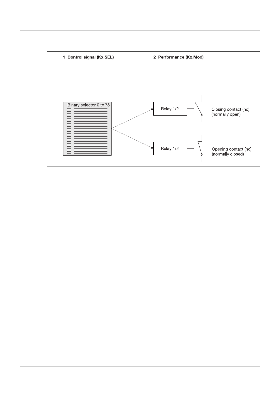
Relay outputs 1 to 2
Figure 30: Behavior of the relay outputs 1 to 2
Performance (Kx.Mod)
This function defines how therelay output is operated. N/C and N/O contacts are available (see
Figure 30, item 2). Not every receiver type provides relay outputs.
Chapter 2.2 "Order details", page 10
Control signal (Kx.SEL)
The control signal (see Figure 30, item 1) defines the status used to switch relay output 1 or 2.
The following conditions can be set in the binary selector:
Relay output inactive (not assigned)
The relays remain in their configured basic status (no/nc).
Wireless timeout, channel 1 to 16
A relay is switched when the wireless timeout is exceeded.
The wireless timeout is a configurable alarm bit which is set when the wireless signal of a linked
transmitter has not been received for a long time.
Analog alarm 1 and 2, channel 1 to 16
A relay is switched when limit value alarm 1 or 2 is activated.
Low battery, channel 1 to 16
A relay is switched when a transmitter battery needs to be replaced.
Relay status 1 and 2
A relay is switched when it is accessed by another relay.
Due to the fact that the relay outputs in the receiver have only two pins, it is possible to make
one changeover contact out of two relays: for example relay 2 is configured as a logical inverter
(N/C contact).