8 configuring the receiver – JUMO 902931 Wtrans Receiver with Wireless Data Transmission Operating Manual User Manual
Page 59
59
8 Configuring the receiver
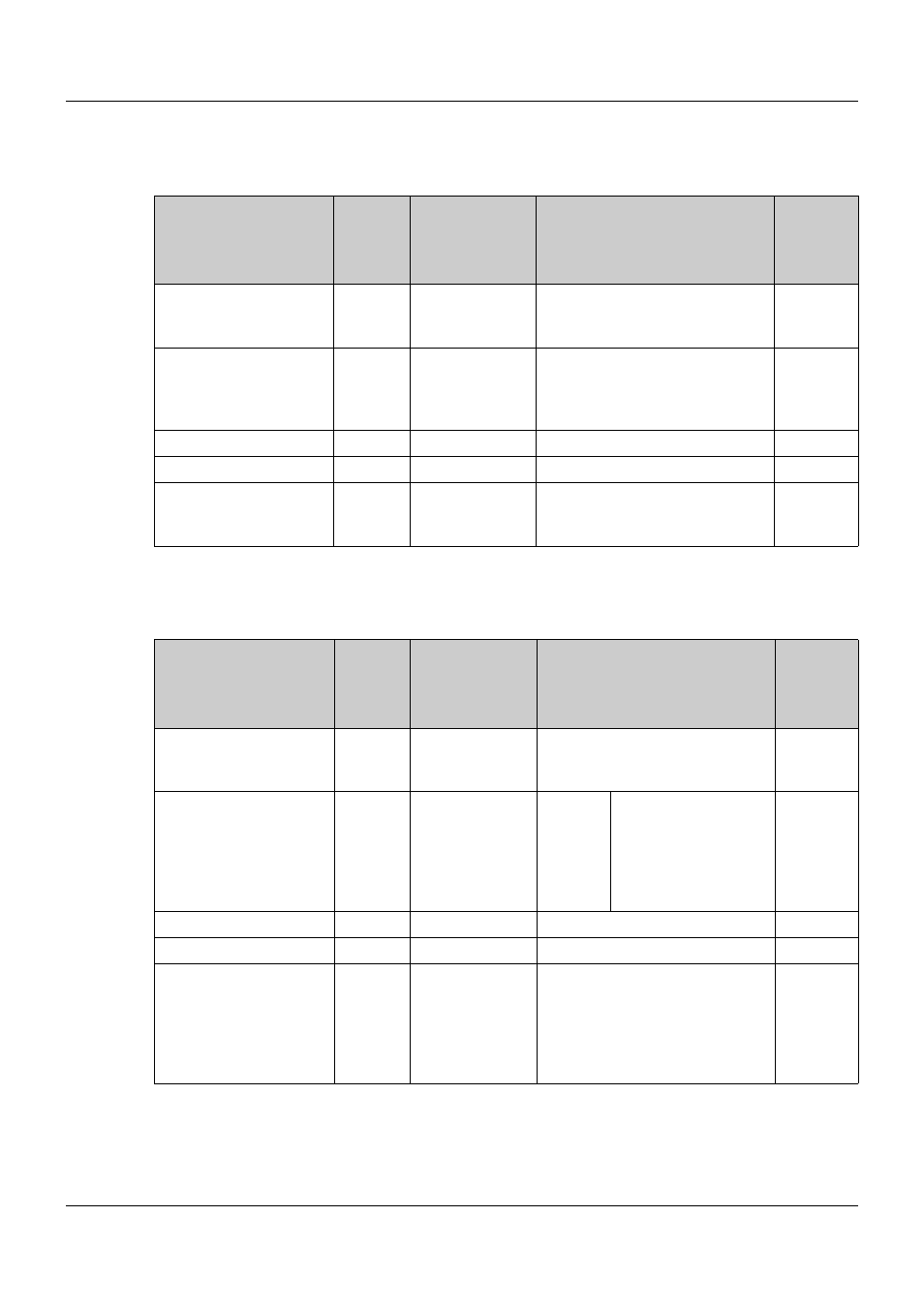
RS485 interface
The following table displays the RS485 interface parameters to be set. The setup connector is
operated with fixed parameters, irrespectively of these parameters.
Analog outputs 1 to 4
The following table shows the parameters of analog output 1 that are to be set. Identical setting
options apply for analog outputs 2 to 4 (for type T01.EC3 analog outputs 3 and 4).
Parameter
Bottom
line
of dis-
play
Top
line
of display
Value range/selection
Baud rate
485.Bd
9600
19.2
38.4
9600 bit/s
19200 bit/s
38400 bit/s
Data format
(data bits/parity/
stop bits)
485.Fo
8n1
8o1
8E1
8n2
8/none/1
8/odd/1
8/even/1
8/none/2
Minimum response time 485.tA
30
0 to 500 ms
Device address
485.Ad
1
1 to 254
Customer replacement
actual values
in the event of an error
485.Er
0
-9999 to +9999
Parameter
Bottom
line
of dis-
play
Top
line
of display
Value range/selection
Output signal type
A1.Mod
0-20
4-20
0-10
0 to 20 mA
4 to 20 mA
0 to 10 V
Output variable
(analog selector)
A1.SEL
1
0
1 to 16
17 to 20
No analog value
Actual value channel
1 to 16
Modbus remote con-
trol values analog 1 to
4
Zero point
A1.Zer
-30
-9999 to +9999
End point
A1.End
+260
-9999 to +9999
Error behavior
A1.Err
ErLo
ErHi
Negative signaling:
< -0.1 mA/< 3.6 mA/< -0.1 V
Positive signaling:
> 21 mA/> 21 mA/> 10.5 V
(depending on the output signal
type)