9 term definition, 2 channel-specific parameters – JUMO 902931 Wtrans Receiver with Wireless Data Transmission Operating Manual User Manual
Page 73
73
9 Term definition
9.2
Channel-specific parameters
Wireless telegram timeout [Wireless timeout (xx.Tmo)]
This is the number of transmitter intervals during which one new probe value must have arrived.
The set transmission interval of the transmitter is transmitted with the wireless telegram. When
the first telegram is received, this value is saved in the receiver and the wireless timeout mon-
itoring function is activated.
If no new value from the transmitter is received throughout the entire timeout period, the mea-
sured value is set to "no input value", the alarm bit "Wireless timeout" of the channel is set, and
the top LED flashes red.
Offset (xx.OFF)
This offset value (actual value correction) is added to the measured input value with the correct
sign. This permits a correction in the "+" as well as the "-" direction.
Examples:
Filter time constant (xx.dF)
This parameter is used to adapt the digital input filter to the task. In the event of a signal jump,
63 % of the alterations are acquired after 2 filter time constants. If the filter time is long, it
means:
•
High attenuation of interference signals
•
Slow reaction of the actual value display to actual value changes
•
Low limit frequency (2nd order low-pass filter)
Decimal place (xx.dP)
The position of the decimal point is selected here. Between 0 and 2 decimal places can be se-
lected or the automatic display (one decimal place as standard) can be used.
If the actual value exceeds the measurand that can be displayed with the decimal places, the
decimal place(s) are not used.
Customer-specific linearization
Four customer-specific linearizations are available in addition to the linearization that follows
the input signal in a linear manner. The corresponding linearization tables must be created with
the setup program.
In order to use the customer-specific linearization, a suitable transmitter must be linked and the
transmitter sensor type must be configured as Resistance transmitter, Potentiometer, Voltage,
or Pressure.
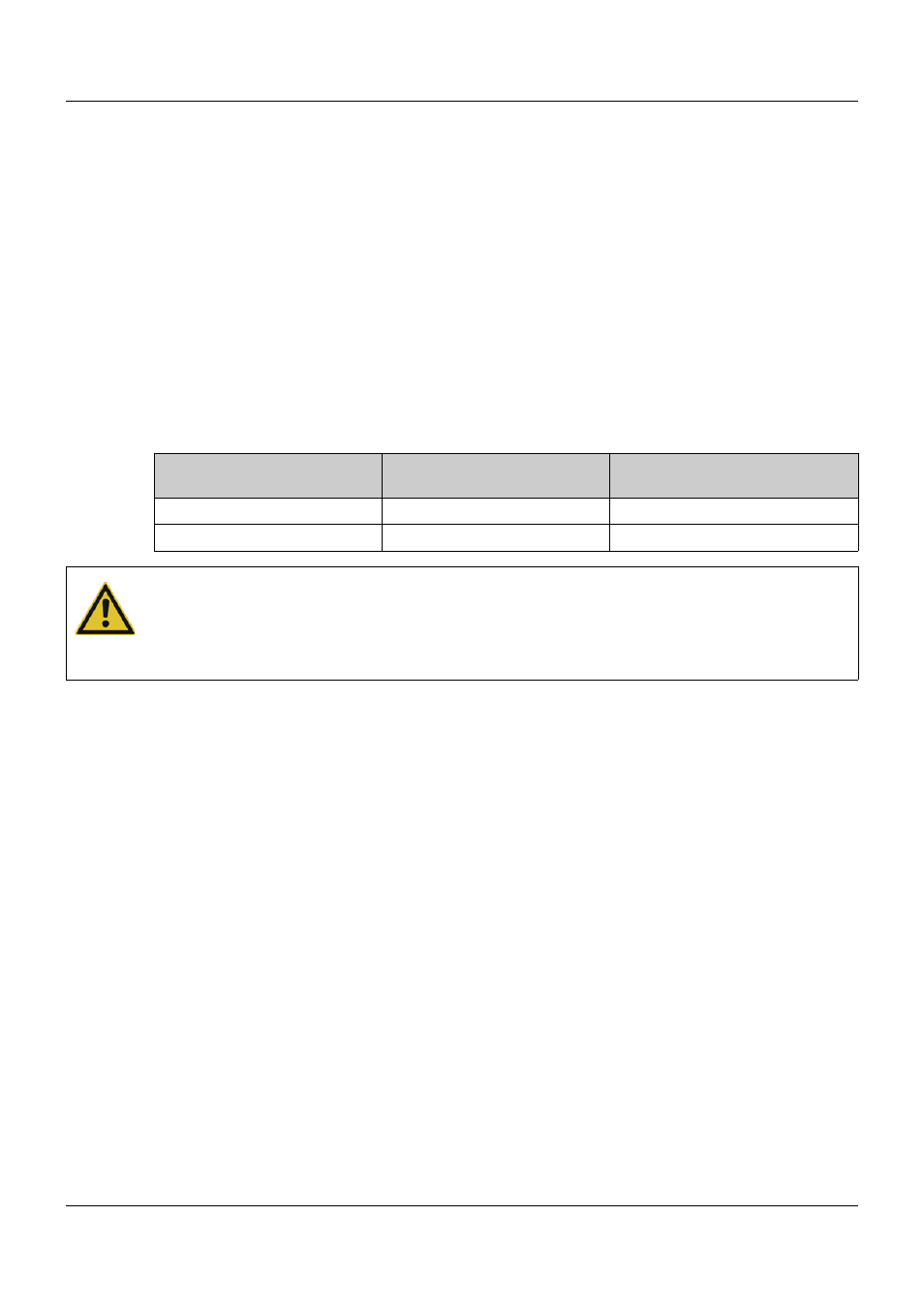
Measured value
Offset (actual value correc-
tion)
Displayed value
294.7
+0.3
295.0
295.3
-0.3
295.0
CAUTION!
After an offset change, you should perform the following steps if necessary:
1. Reset the drag indicator.
2. Check the scaling of the analog outputs.
3. Check the settings of the limit value alarms.