Horner APG XL4 OCS User Manual
Page 99
MAN0964-01-EN
CH.16
June 29, 2012
Page 99 of 122
The Q1 and Q2 group boxes allow the user to specify the operation of the multi-function outputs.
The PWM State On Controller Stop group box contains items that allow the user to specify how the
PWM outputs behave when the controller is stopped. These items can either hold their value or default to
some value when the controller is stopped.
Note that the PWM outputs are set to the OFF state at power-up and during program download
and remain in that state until the unit is placed in RUN
The Output State On Controller Stop group box contains items to allow the user to specify how the
remaining digital outputs behave when the controller is stopped. These items can either hold their value
or default to some value when the controller is stopped.
15.8
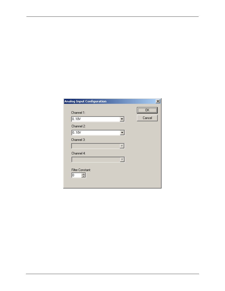
Analog Input Configuration
The following figure illustrates the Analog Input Configuration dialog.
Figure 15.4 – Analog Input Configuration Dialog
The Channel x drop down windows allow the user to specify the mode for each analog input to operate.
The Channel x drop down windows are enabled/disabled according to which model is being configured.
All of the models have the following modes available:
-
0..10V
-
0..20mA
-
4..20mA
On model 005, channels 3 and 4 also have the following modes available:
-
100mV
-
PT100 DIN RTD, 1/20
°c
-
Type J Thermocouple, 1/20
°c
-
Type K Thermocouple, 1/20
°c