Horner APG XL4 OCS User Manual
Page 56
CH.11
MAN0964-01-EN
June 29, 2012
Page 56 of 122
Error
A high indication on this register indicates that one of the analog parameters specified
above is invalid or the stepper action was aborted before the operation was complete.
This register is cleared on the next start command if the error was corrected.
The stepper requires one discrete register to control the stepper action. Setting this register
starts the stepper cycle. This register must remain set to complete the entire cycle. Clearing this
register before the cycle is complete aborts the step sequence and sets the error bit.
Note that setting the PLC mode to Stop while the stepper is in operation causes the
stepper output to immediately drop to zero and the current stepper count to be lost.
Note that stepper output level may cause damage or be incompatible with some motor
driver inputs. Consult drive documentation to determine if output level and type is
compatible.
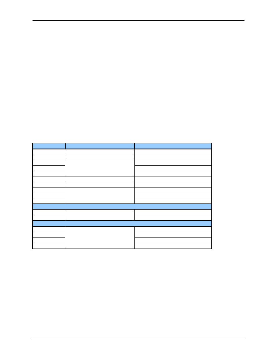
11.5
PWM functions register map
The register assignments for the high speed I/O can be moved via a setting in Cscape. The values
shown are the DEFAULT values and may not match the same starting point as the values shown below.
Register
PWM
Stepper
%AQ421-422
PWM 1 Duty Cycle (32-bit)
Start Frequency – Stepper 1
%AQ423-424
PWM 1 Frequency
Run Frequency – Stepper 1
%AQ425-426
Acceleration Count – Stepper 1
%AQ427-428
Run Count – Stepper 1
%AQ429-430
Deceleration Count – Stepper 1
%AQ431-432
PWM 2 Duty Cycle (32-bit)
Start Frequency – Stepper 2
%AQ433-434
PWM 2 Frequency
Run Frequency – Stepper 2
%AQ435-436
Acceleration Count – Stepper 2
%AQ437-438
Run Count – Stepper 2
%AQ439-440
Deceleration Count – Stepper 2
%Q1
Digital Out – Stepper 1
%Q2
Digital Out – Stepper 2
%I1617
Ready/Done – Stepper 1
%I618
Error – Stepper 1
%I1619
Ready/Done – Stepper 2
%I620
Error – Stepper 2