Horner APG XL4 OCS User Manual
Page 44
CH.10
MAN0964-01-EN
June 29, 2012
Page 44 of 122
10.4
Solid-State Digital Outputs
Solid-state digital outputs are generally used to activate lamps, low voltage solenoids, relays and other
low voltage and low current devices.
Note: The digital outputs used on the XL4 OCS are “sourcing” outputs. This means the output applies a
positive voltage to the output pin when turned ON. When turned off, the output applies approximately zero
volts with respect to the I/O ground.
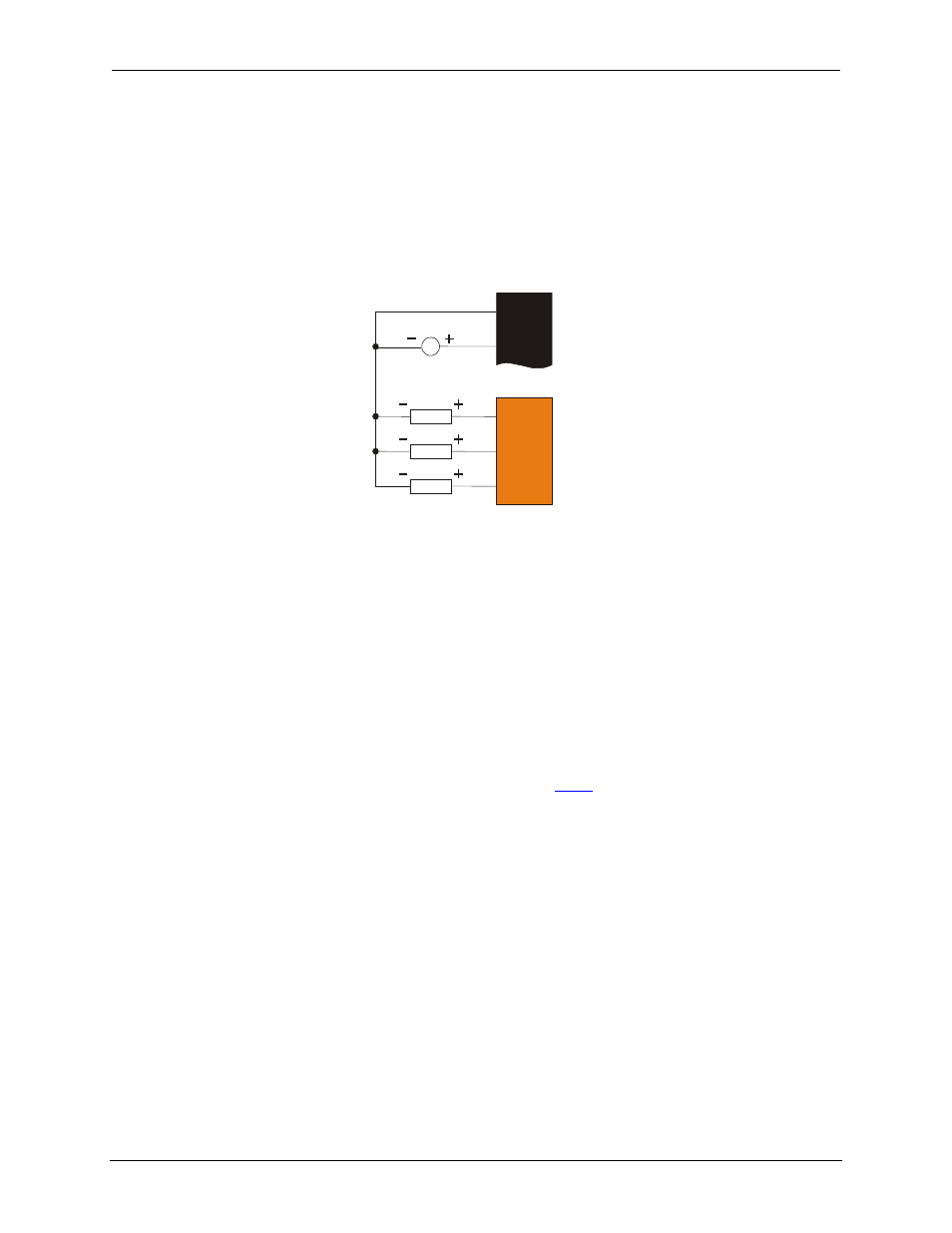
Figure 10.5 – Typical Output Wiring
The digital outputs used in the XL4 OCS have electronic short circuit protection and current limiting.
While these electronic protections work in most applications, some application may require external
fusing on these outputs.
The digital outputs in the XL4 OCS are typically controlled via %Q bits in the register mapping. Some of
the outputs are designed for high-speed applications and can be used for PWM or frequency output
applications. Please see the data sheet and the chapter on High Speed I/O for additional information.
When the controller is stopped the operation of each output is configurable. The outputs can hold the
state they were in before the controller stopped or they can go to a predetermined state. By default digital
outputs turn off. For more information on stop state see the
Index
to find pages referencing Cscape
settings.
The digital outputs feature an output fault bit. %I32 will turn on if any of the outputs experience a short
circuit, over-current or the output driver overheats.
10.5
Relay Outputs
Relay outputs are designed to switch loads that typically have high voltage or current requirements or
require isolation that relays provide.
Note: The design of the XL4 OCS does not require external coil power for the relays to function. The
relays will activate anytime the XL4 OCS is powered.
There are several factors that should be considered when using relays.
Q14
Q15
V+
0V
LOAD
LOAD
10 - 30VDC
Q16
LOAD
J2
J4