12 parallel port interface signals – AMD Geode SC2200 User Manual
Page 62
66
AMD Geode™ SC2200 Processor Data Book
32580B
3.4.12
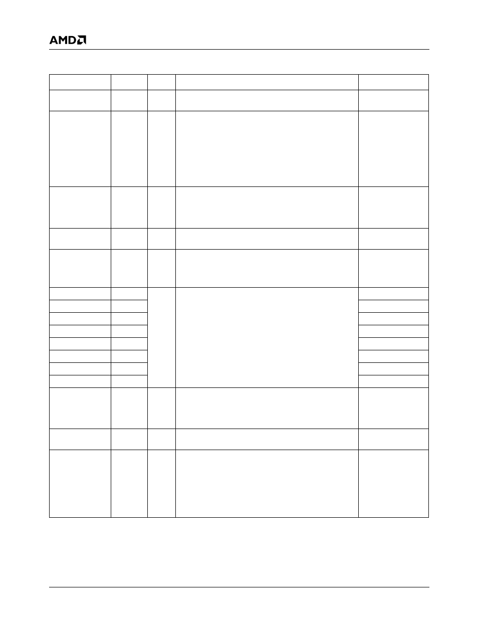
Parallel Port Interface Signals
Signal Name
Ball No.
Type
Description
Mux
ACK# B18
I
Acknowledge. Pulsed low by the printer to indicate that it
has received data from the Parallel Port.
TFTDE+FPCICLK
AFD#/DSTRB# D22
O
Automatic Feed. When low, instructs the printer to auto-
matically feed a line after printing each line. This signal is
in TRI-STATE after a 0 is loaded into the corresponding
control register bit. An external 4.7 K
Ω pull-up resistor
should be attached to this ball.
Data Strobe (EPP). Active low, used in EPP mode to
denote a data cycle. When the cycle is aborted, DSTRB#
becomes inactive (high).
TFTD2+INTR_O
BUSY/WAIT#
B17
I
Busy. Set high by the printer when it cannot accept
another character.
Wait. In EPP mode, the Parallel Port device uses this
active low signal to extend its access cycle.
TFTD3+F_C/BE1#
ERR#
D21
I
Error. Set active low by the printer when it detects an
error.
TFTD4+F_C/BE0#
INIT#
B21
O
Initialize. When low, initializes the printer. This signal is
in TRI-STATE after a 1 is loaded into the corresponding
control register bit. Use an external 4.7 K
Ω pull-up resis-
tor.
TFTD5+SMI_O
PD7
A18
I/O
Parallel Port Data. Transfer data to and from the periph-
eral data bus and the appropriate Parallel Port data regis-
ter. These signals have a high current drive capability.
TFTD13+F_AD7
PD6
A20
TFTD1+F_AD6
PD5
C19
TFTD11+F_AD5
PD4
C18
TFTD10+F_AD4
PD3
C20
TFTD9+F_AD3
PD2
D20
TFTD8+F_AD2
PD1
A21
TFTD7+F_AD1
PD0
C21
TFTD6+F_AD0
PE
D17
I
Paper End. Set high by the printer when it is out of
paper.
This ball has an internal weak pull-up or pull-down resis-
tor that is programmed by software.
TFTD14+F_C/BE2#
SLCT
C17
I
Select. Set active high by the printer when the printer is
selected.
TFTD15+F_C/BE3#
SLIN#/ASTRB# B20
O
Select Input. When low, selects the printer. This signal
is in TRI-STATE after a 0 is loaded into the corresponding
control register bit. Uses an external 4.7 K
Ω pull-up resis-
tor.
Address Strobe (EPP). Active low, used in EPP mode to
denote an address or data cycle. When the cycle is
aborted, ASTRB# becomes inactive (high).
TFTD16+
F_IRDY#