Figure 9-14, Pciclk timing and measurement points, Table 9-24 – AMD Geode SC2200 User Manual
Page 375: Pci clock parameters
AMD Geode™ SC2200 Processor Data Book
393
Electrical Specifications
32580B
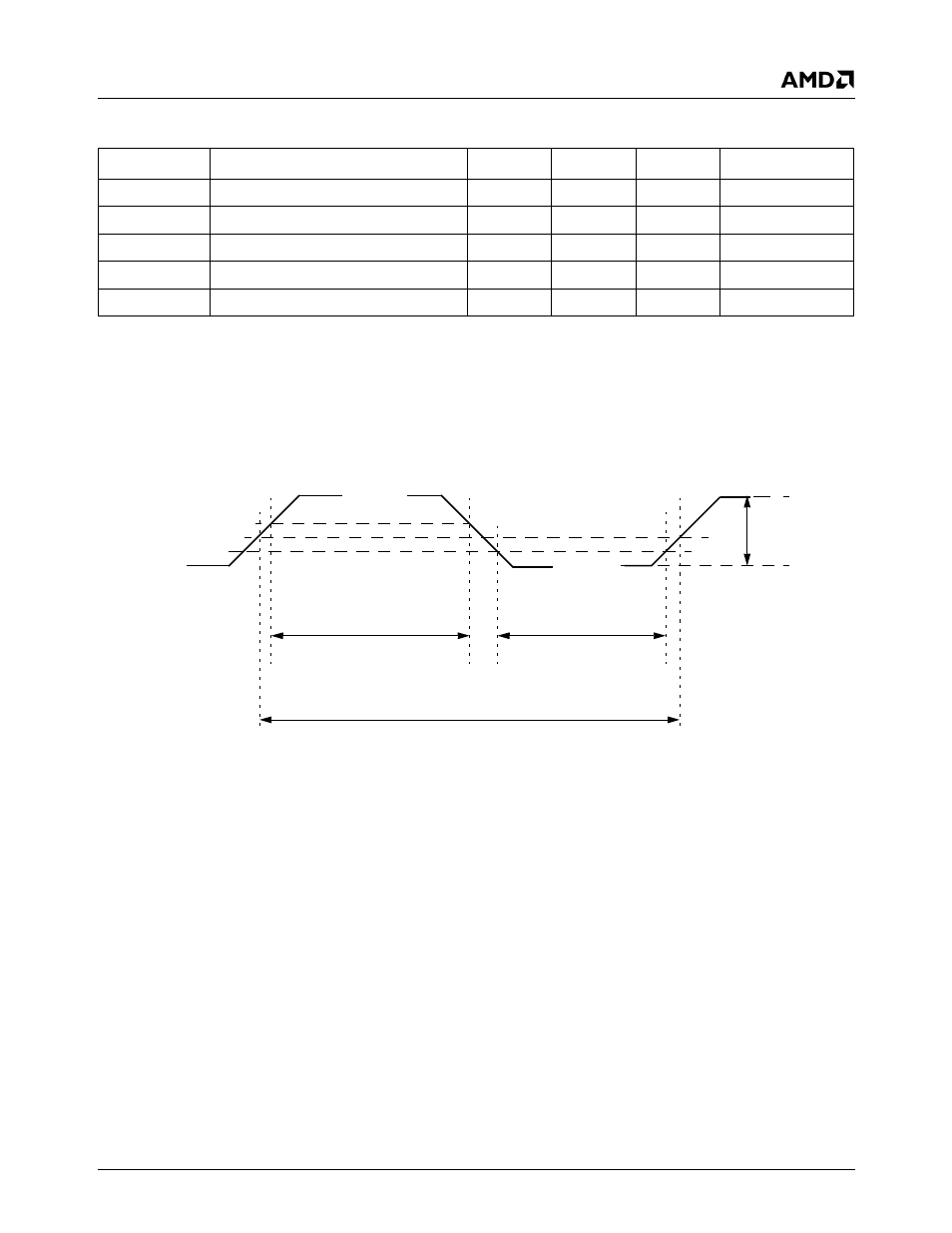
Figure 9-14. PCICLK Timing and Measurement Points
Table 9-19. PCI Clock Parameters
Symbol
Parameter
Min
Max
Unit
Comments
t
CYC
PCICLK cycle time
30
ns
Note 1
t
HIGH
PCICLK high time
11
ns
Note 2
t
LOW
PCICLK low time
11
ns
Note 2
PCICLK
sr
PCICLK slew Rate
1
4
V/ns
Note 3
PCIRST
sr
PCIRST# slew Rate
50
-
mV/ns
Note 4
Note 1. Clock frequency is between nominal DC and 33 MHz. Device operational parameters at frequencies under 16 MHz
are not 100% tested. The clock can only be stopped in a low state.
Note 2. Guaranteed by characterization.
Note 3. Slew rate must be met across the minimum peak-to-peak portion of the clock waveform (see Figure 9-14).
Note 4. The minimum PCIRST# slew rate applies only to the rising (de-assertion) edge of the reset signal. See Figure 9-18
for PCIRST# timing.
t
HIGH
0.4 V
IO
, p-to-p
(minimum)
0.6V
IO
0.2V
IO
0.5 V
IO
0.4 V
IO
0.3 V
IO
t
CYC
t
LOW
PCICLK