4 crt/tft interface signals, 5 access.bus interface signals – AMD Geode SC2200 User Manual
Page 52
56
AMD Geode™ SC2200 Processor Data Book
32580B
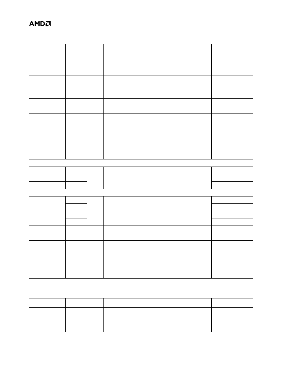
3.4.4
CRT/TFT Interface Signals
Signal Name
Ball No.
Type
Description
Mux
DDC_SCL
Y1
O
DDC Serial Clock. This is the serial clock for the VESA
Display Data Channel interface. It is used for monitor
communications. The DDC2B standard is supported by
this interface.
IDE_DATA10
DDC_SDA
Y2
I/O
DDC Serial Data. This is the bidirectional serial data sig-
nal for the VESA Display Data Channel interface. It is
used for monitor communications. The DDC2B standard
is supported by this interface.
IDE_DATA9
HSYNC
A11
O
Horizontal Sync
---
VSYNC
B11
O
Vertical Sync
---
VREF
D16
I/O
Voltage Reference. Reference voltage for CRT PLL and
DAC. This signal reflects the internal voltage reference. If
internal voltage reference is used (recommended), leave
this ball disconnected. If an external voltage reference is
used, this input is tied to a 1.235V reference.
---
SETRES
B15
I
Set Resistor. This signal sets the current level for the
RED/GREEN/BLUE analog outputs. Typically, a 464
Ω,
1% resistor is connected between this ball and AV
SSCRT
.
---
On-Chip RAMDAC
RED
B12
O
Analog Red, Green and Blue
---
GREEN
A14
---
BLUE
A15
---
TFT (External DAC) Interface
TFTDCK
AA1
O
TFT Clock. Clock to external CRT DACs or TFT.
IDE_RST#
A10
GPIO17+ IOCS0#
TFTDE
P2
O
TFT Data Enable. Can be used as blank signal to exter-
nal CRT DACs.
IDE_CS1#
B18
ACK#+FPCICLK
FP_VDD_ON
AB1
O
TFT Power Control. Used to enable power to the Flat
Panel display, with power sequence timing.
IDE_DATA4
V30
GXCLK+TEST3
TFTD[17:0]
See
O
Digital RGB Data to TFT.
TFTD[5:0] - Connect to BLUE TFT inputs.
TFTD[11:6] - Connect to GREEN TFT inputs.
TFTD[17:12] - Connect to RED TFT inputs.
The TFT interface is
muxed with the IDE
interface or the Par-
allel Port. See Table
3-5 on page 46 and
48 for details.
3.4.5
ACCESS.bus Interface Signals
Signal Name
Ball No.
Type
Description
Mux
AB1C
N31
I/O
ACCESS.bus 1 Serial Clock. This is the serial clock for
the interface.
Note:
If selected as AB1C function but not used, tie
AB1C high.
GPIO20+DOCCS#