4 signal descriptions, 1 system interface, Section 3.4 "signal descriptions – AMD Geode SC2200 User Manual
Page 48
52
AMD Geode™ SC2200 Processor Data Book
32580B
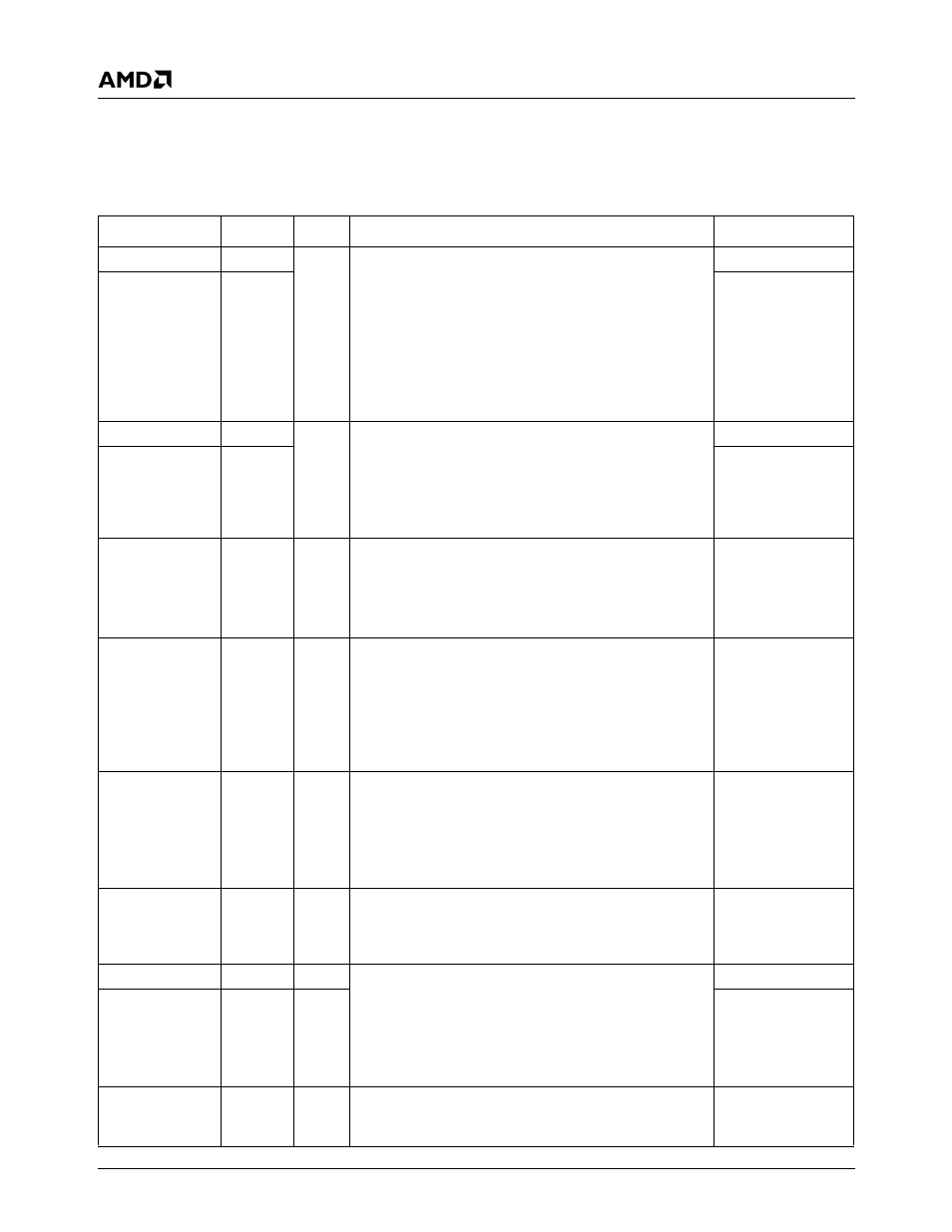
3.4
Signal Descriptions
Information in the tables that follow may have duplicate information in multiple tables. Multiple references all contain identi-
cal information.
3.4.1
System Interface
Signal Name
Ball No.
Type
Description
Mux
CLKSEL1
AF3
I
Fast-PCI Clock Selects. These strap signals are used to
set the internal Fast-PCI clock.
00 = 33.3 MHz
01 = 48 MHz
10 = 66.7 MHz
11 = 33.3 MHz
During system reset, an internal pull-down resistor of 100
K
Ω exists on these balls. An external pull-up or pull-down
resistor of 1.5 K
Ω must be used.
SOUT1
CLKSEL0
B8
RD#
CLKSEL3
P30
I
Maximum Core Clock Multiplier. These strap signals
are used to set the maximum allowed multiplier value for
the core clock.
During system reset, an internal pull-down resistor of 100
K
Ω exists on these balls. An external pull-up or pull-down
resistor of 1.5 K
Ω must be used.
SYNC
CLKSEL2
D29
SOUT2
BOOT16
C8
I
Boot ROM is 16 Bits Wide. This strap signal enables
the optional 16-bit wide Sub-ISA bus.
During system reset, an internal pull-down resistor of 100
K
Ω exists on these balls. An external pull-up or pull-down
resistor of 1.5 K
Ω must be used.
ROMCS#
LPC_ROM
D6
I
LPC_ROM. This strap signal forces selecting of the LPC
bus and sets bit F0BAR1+I/O Offset 10h[15], LPC ROM
Addressing Enable. It enables the SC2200 to boot from a
ROM connected to the LPC bus.
During system reset, an internal pull-down resistor of 100
K
Ω exists on these balls. An external pull-up or pull-down
resistor of 1.5 K
Ω must be used.
PCICLK1
TFT_PRSNT
P29
I
TFT Present. A strap used to select multiplexing of TFT
signals at power-up. Enables using TFT instead of Paral-
lel Port, ACB1, and GPIO17.
During system reset, an internal pull-down resistor of 100
K
Ω exists on these balls. An external pull-up or pull-down
resistor of 1.5 K
Ω must be used.
SDATA_OUT
FPCI_MON
A4
I
Fast-PCI Monitoring. The strap on this ball forces selec-
tion of Fast-PCI monitoring signals. For normal operation,
strap this signal low using a 1.5 K
Ω resistor. The value of
this strap can be read on the MCR[30].
PCICLK0
DID1
C6
I
Device ID. Together, the straps on these signals define
the system-level chip ID.
The value of DID1 can be read in the MCR[29]. The
value of DID0 can be read in the MCR[31].
DID0 must have a pull-up resistor of 1.5 K
Ω and DID1
must have a pull-down resistor of 1.5 K
Ω.
GNT1#
DID0
C5
I
GNT0#
POR#
AH9
I
Power On Reset. POR# is the system reset signal gen-
erated from the power supply to indicate that the system
should be reset.
---