AMD Geode SC2200 User Manual
Page 279
AMD Geode™ SC2200 Processor Data Book
291
Core Logic Module - X-Bus Expansion Interface - Function 5
32580B
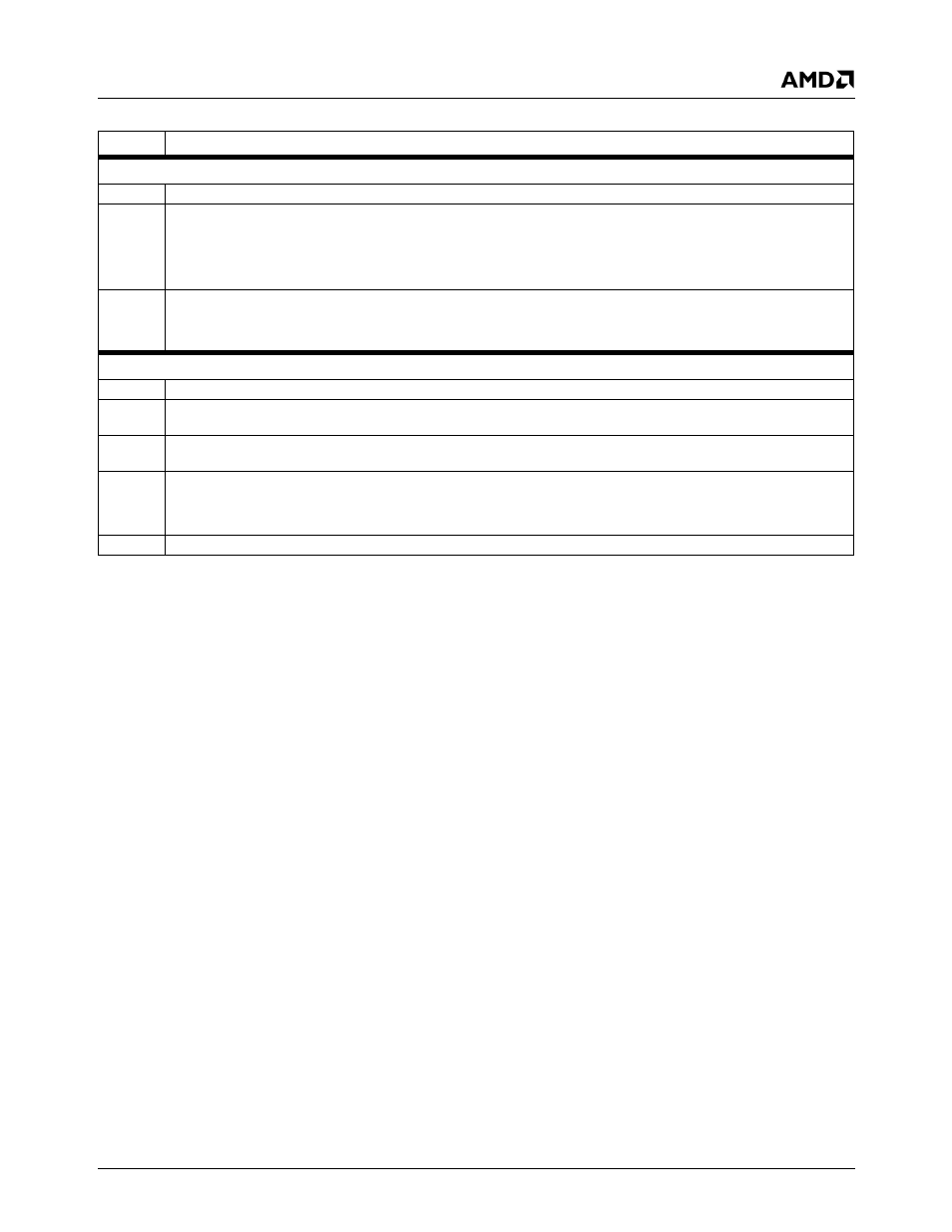
Offset 04h-07h
I/O Control Register 2 (R/W)
Reset Value: 00000002h
31:2
Reserved. Write as read.
1
Video Processor Access Enable. Allows access to video processor using F4BAR0.
0: Disable.
1: Enable. (Default)
Note:
This bit is readable after the register (F5BAR0+Offset 04h) has been written once.
0
IO_STRAP_IDSEL_SELECT (IDSEL Strap Override).
0: IDSEL: AD28 for Chipset Register Space (F0-F5), AD29 for USB Register Space (PCIUSB).
1: IDSEL: AD26 for Chipset Register Space (F0-F5), AD27 for USB Register Space (PCIUSB).
Offset 08h-0Bh
I/O Control Register 3 (R/W)
Reset Value: 00009000h
31:16
Reserved. Write as read.
15:13
IO_USB_XCVR_VADJ (USB Voltage Adjustment Connection). These bits connect to the voltage adjustment interface on
the three USB transceivers. Default = 100.
12:8
IO_USB_XCVT_CADJ (USB Current Adjustment). These bits connect to the current adjustment interface on the three
USB transceivers. Default = 10000.
7
IO_TEST_PORT_EN (Debug Test Port Enable).
0: Disable.
1: Enable.
6:0
IO_TEST_PORT_REG (Debug Port Pointer). These bits are used to point to the 16-bit slice of the test port bus.
Table 6-40. F5BAR0+I/O Offset: X-Bus Expansion Registers (Continued)
Bit
Description