Figure 7-5 – AMD Geode SC2200 User Manual
Page 313
AMD Geode™ SC2200 Processor Data Book
325
Video Processor Module
32580B
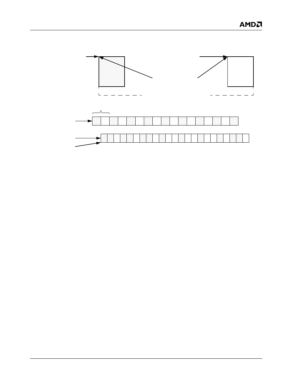
Figure 7-5. Capture Video Mode Bob Example Using One Video Frame Buffer
Weave
The Weave method assembles the odd field and even field
together to form the complete frame, and then renders the
“weaved” frames to the display device. The Video data is
converted from interlaced to progressive. Since both fields
are rendered simultaneously, the GX1 module’s video
frame buffer must be at least double buffered. The Weave
method has the advantage of not creating the temporal
effects that Bob does. The disadvantage of Weave is twice
as much data is transferred from the video frame buffer to
the Video Processor; meaning that Weave uses more
memory bandwidth.
Figure 7-6 on page 326 is an example of the Weave
method in action. As in the Bob example (Figure 7-5), a
CRT monitor at 85 Hz refresh is assumed. Double buffering
of the incoming data is also assumed. The example does
not assume anything about any scaling that may be done in
the Video Processor. No attempt has been made to assure
that this example is absolutely workable. The example is
only presented to allow for a general understanding of how
the SC2200’s video support hardware works.
The following procedure is an example of how to create the
Weave method. Since at least double buffering is required,
more of the VIP’s control registers are used for Weave than
required for Bob during video runtime.
1)
Program the VIP bus master address registers.
Three registers control where the VIP video data is
stored in the GX1 module’s frame buffer:
– F4BAR2+Memory Offset 20h – Video Data Odd
Base Address
– F4BAR2+Memory Offset 24h – Video Data Even
Base Address
– F4BAR2+Memory Offset 28h – Video Data Pitch
The Video Data Even Base Address must be sepa-
rated from the Video Data Odd Base Address by one
horizontal line. The Video Data Pitch register must be
programmed to one horizontal line.
2)
Program other VIP bus master support registers.
Ensure the VIP FIFO Bus Request Threshold is set to
32 bytes (F4BAR2+Memory Offset 00h[22] = 1) and
the Video Input Port mode is set to CCIR-656
(F4BAR2+Memory Offset 00h[1:0] = 10). An interrupt
needs to be generated so that the GX1 module’s video
frame buffer pointer can flip to the field that has com-
pleted transfer to the video frame buffer. So the Field
Interrupt bit (F4BAR2+Memory Offset 04h[16] = 1).
must be enabled. Auto-Flip is normally set
(F4BAR2+Memory Offset 04h[10] = 0) to allow the
CCIR-656 decoder to identify which field is being pro-
cessed. Capture video data needs to be enabled
(F4BAR2+Memory Offset 04h[10] = 1) and Run Mode
Capture is set to Start Capture (F4BAR2+Memory Off-
set 04h[1:0] = 11) at beginning of next field. Data is
now being captured to the frame buffer.
Video Data Odd Base
Video Data Even Base
DC_VID_ST_OFFSET
Odd
Field
Even
Field
GX1 Module’s Video Frame Buffer
1
2
3
4
5
6
7
8
9
10
11
12
13
14
15
16
17
1
2
3
4
6
7
8
9 10 11 12 13 14 15 16 17 18 19 20
22 23
Capture video fill
Video subsystem
85 frames per second
5
5
21
30 frames per second
(F4BAR2+Memory Offset 24h)
Address not changed during runtime
(GX_BASE+Memory Offset 8320h)
Ping-pongs between the two buffers during runtime
(F4BAR2+Memory Offset 20h)
Address not changed
during runtime
Buf #1
sequence
empty sequence