AMD Geode SC2200 User Manual
Page 347
AMD Geode™ SC2200 Processor Data Book
359
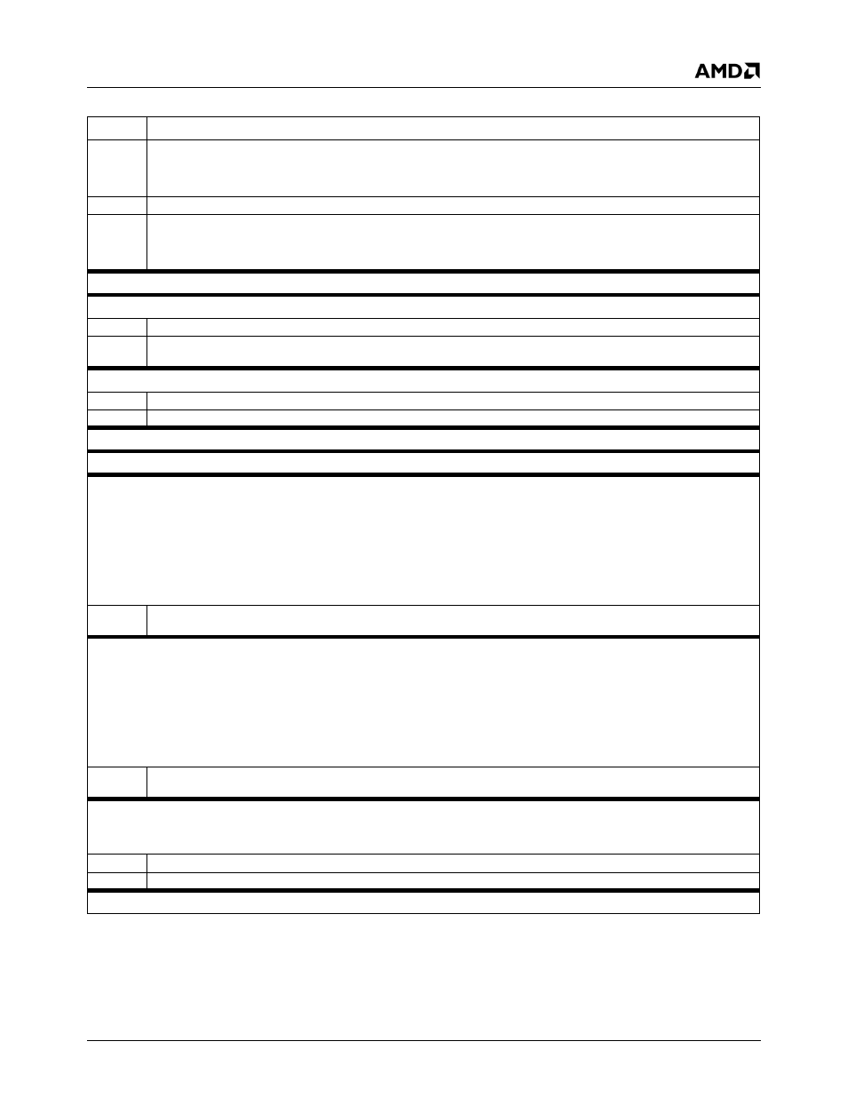
Video Processor Module - Video Processor Registers - Function 4
32580B
8
Video Data Capture Active. (Read Only)
0: Video data is not being stored to memory.
1: Video data is now being stored to memory.
7:1
Reserved. (Read Only)
0
Run Status. (Read Only)
0: Video port capture is not active.
1: Video port capture is in progress.
Offset 0Ch-0Fh
Reserved
Reset Value: 00h
Offset 10h-13h
Video Current Line Register (RO)
Reset Value: xxxxxxxxh
31:10
Reserved.
9:0
Current Line. Indicates the video line currently being stored to memory. The count indicated in this field is reset to 0 at the
start of each field.
Offset 14h-17h
Video Line Target Register (R/W)
Reset Value: 00000000h
31:10
Reserved. Must be set to 0.
9:0
Line Target. Indicates the video line to generate an interrupt on.
Offset 18h-1Bh
Reserved
Reset Value: 00000000h
Offset 1Ch-1Fh
Reserved
Reset Value: 00000000h
Offset 20h-23h
Video Data Odd Base Register (R/W)
Reset Value: 00000000h
This register specifies the base address in graphics memory where odd video field data are stored. Changes to this register take effect
at the beginning of the next field. The value in this register is 16-byte aligned.
Note:
This register is double-buffered. When a new value is written to this register, the new value is placed in a special "pending" reg-
ister, and the "Base Register Not Updated" bit (F4BAR2+MemoryOffset 08h[21]) is set to 1. The Video Data Odd Base register
(this register) is not updated at this point. When the first data of the next field is stored to memory, the pending values of all
base registers (including this one) are written to the appropriate base registers, and the "Base Register Not Updated" bit is
cleared.
31:0
Video Odd Base Address. Base address where odd video data are stored in graphics memory. Bits [3:0] are always 0, and
define the required address space.
Offset 24h-27h
Video Data Even Base Register (R/W)
Reset Value: 00000000h
This register specifies the base address in graphics memory where even video field data are stored. Changes to this register take effect
at the beginning of the next field. The value in this register is 16-byte aligned.
Note:
This register is double-buffered. When a new value is written to this register, the new value is placed in a special "pending" reg-
ister, and the "Base Register Not Updated" bit (F4BAR2+MemoryOffset 08h[21]) is set to 1. The Video Data Even Base register
(this register) is not updated at this point. When the first data of the next field is stored to memory, the pending values of all
base registers (including this one) are written to the appropriate base registers, and the "Base Register Not Updated" bit is
cleared.
31:0
Video Even Base Address. Base address where even video data are stored in graphics memory. Bits [3:0] are always 0,
and define the required address space.
Offset 28h-2Bh
Video Data Pitch Register (R/W)
Reset Value: 00000000h
This register specifies the logical width of the video data buffer. This value is added to the start of the line address to get the address of
the next line where video data are stored to memory. This value must be an integral number of DWORDs.
31:16
Reserved.
15:0
Video Data Pitch. Specifies the logical width of the video data buffer. Bits [1:0] are always 0.
Offset 2Ch-3Fh
Reserved
Reset Value: 00000000h
Table 7-8. F4BAR2+Memory Offset: VIP Configuration Registers (Continued)
Bit
Description