4 dc current measurements, Table 9-5, Table 9-6 – AMD Geode SC2200 User Manual
Page 354: Dc characteristics for on state
372
AMD Geode™ SC2200 Processor Data Book
Electrical Specifications
32580B
9.1.5.3
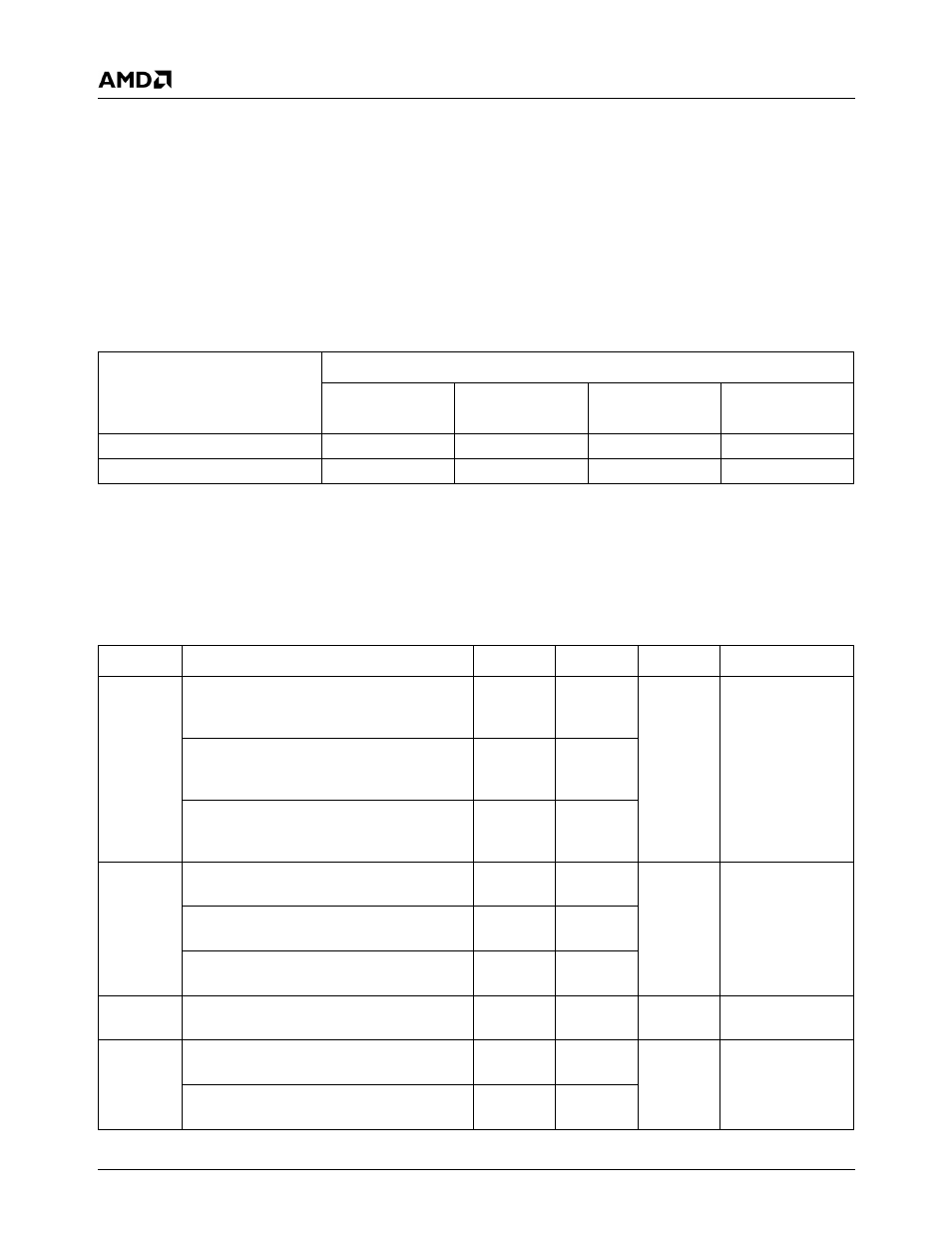
Definition of System Conditions for
Measuring On Parameters
The SC2200’s current is highly dependent on two func-
tional characteristics, DCLK (DOT clock) and SDRAM fre-
quency. Table 9-5 on page 372 shows how these factors
are controlled when measuring the typical average and
absolute maximum processor current parameters.
9.1.5.4
DC Current Measurements
Table 9-6 and Table 9-7 show the DC current measure-
ments of the SC2200. The SC2200 supports CRT and TFT
displays, but it is expected that generally only one display
interface will be used. Power consumed by the SC2200 is
different with different displays. The CRT DAC requires cur-
rent, while the TFT interface even though it has no DAC to
power, also draws current while it is active. The CRT DAC
and the TFT interface are presented as separate line items.
The chosen display type I/O current should be added to the
Typical, Absolute Maximum, and Active Idle I/O currents to
get total current.
Table 9-5. System Conditions Used to Measure SC2200 Current During the On State
CPU Current Measurement
System Conditions
V
CORE
(Note 1)
V
IO
(Note 1)
DCLK Frequency
SDRAM
Frequency
Typical Average
Nominal
Nominal
50 MHz (Note 2)
Nominal
Absolute Maximum
Max
Max
135 MHz (Note 3)
Max
Note 1. See Table 9-3 on page 370 for nominal and maximum voltages.
Note 2. A DCLK frequency of 50 MHz is derived by setting the display mode to 800x600x8 bpp at 75 Hz, using a display
image of vertical stripes (4-pixel wide) alternating between black and white with power management disabled.
Note 3. A DCLK frequency of 135 MHz is derived by setting the display mode to 1280x1024x8 bpp at 75 Hz, using a display
image of vertical stripes (1-pixel wide) alternating between black and white with power management disabled.
Table 9-6. DC Characteristics for On State
Symbol
Parameter (Note 1)
Typ Avg
Abs Max
Unit
Comments
I
CC3ON
f
CLK
= 233 MHz, I/O Current @ V
IO
= 3.3V
(Nominal); CPU state = On, excludes TFT
interface contribution and CRT DAC
230
250
mA
I
CC
for V
IO
f
CLK
= 266 MHz, I/O Current @ V
IO
= 3.3V
(Nominal); CPU state = On, excludes TFT
interface contribution and CRT DAC
240
260
f
CLK
= 300 MHz, I/O Current @ V
IO
= 3.3V
(Nominal); CPU state = On, excludes TFT
interface contribution and CRT DAC
250
270
I
COREON
f
CLK
= 233 MHz, Core Current @ V
CORE
=
1.8V (Nominal); CPU state = On
820
990
mA
I
CC
for V
CORE
f
CLK
= 266 MHz, Core Current @ V
CORE
=
1.8V (Nominal); CPU state = On
900
1090
f
CLK
= 300 MHz, Core Current @ V
CORE
=
2.1V (Nominal); CPU state = On
1100
1400
I
SBON
SB Current @ V
SB
= 3.3V (Nominal); CPU
state = On
1
2
mA
I
SBLON
SBL Current @ V
SBL
= 1.8V (Nominal); CPU
state = On
10
20
mA
SBL Current @ V
SBL
= 2.1V (Nominal); CPU
state = On
10
20