In-Situ TROLL 9500 Operators Manual User Manual
Page 77
70
TROLL 9500 Operator’s Manual
0095110 rev. 007 01/09
12. Remove the Cal Cup, discard the first solution, rinse the Cal Cup
and the front end of the instrument, refill the Cal Cup with the
second solution, and attach it to the instrument.
TIP: The calibration solution may be flushed down the drain
with running water, or saved in a separate container and
used to rinse the next time you calibrate with the same solution.
13. Select Run to begin the stabilization for the second calibration
point. Status indicators and controls are the same as for the first
calibration point (step 10).
For a 3-point calibration, repeat steps 12 and 13.
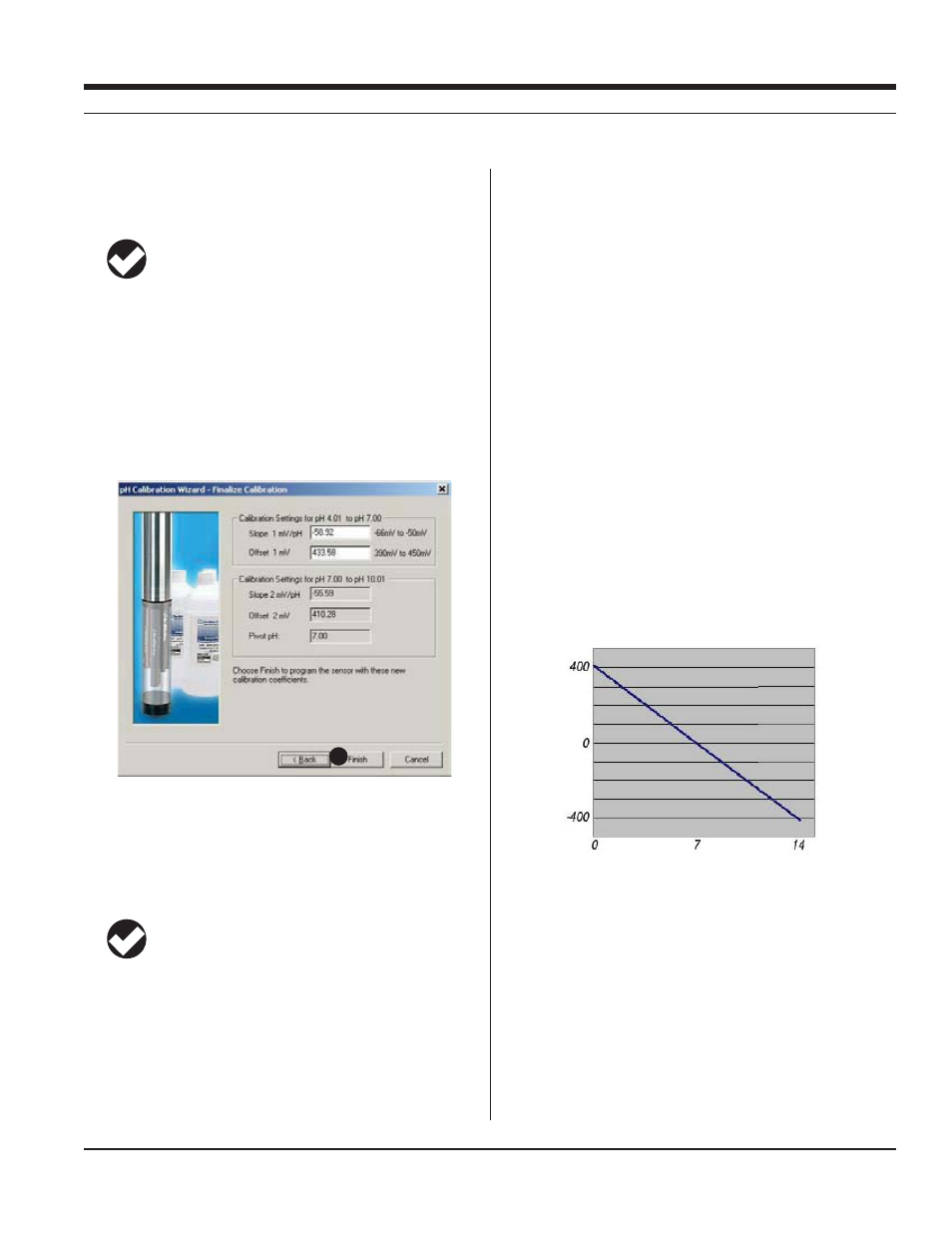
14. The final screen shows the sensor slope and offset calculated
during calibration. For a 3-point calibration, 2 sets of coefficients
will be shown.
“Pivot pH” is the point at which the slope characteristics change
with a 3-point (2-range) calibration. The correct slope for the pH
values being monitored will automatically be applied.
15. Select Finish to program the sensor with the newly calculated
calibration coefficients.
TIP: You can look at the calibration report right after
calibrating, or at any time. See “Calibration History” in
Section 10 for details.
Options for storing the sensor:
s
installed. Remove the Cal Cup and rinse it and the sensors. Add
50-100 mL of tap water to the Cal Cup. Return the probe to the Cal
Cup for transport to the field site.
s
RESETTING DEFAULT COEFFICIENTS
The sensor’s calibration may be reset back to factory defaults at any
time. As the sensor ages, the coefficients calculated during calibra-
tion will deviate more and more from the nominal values, which are
derived from new sensors. Default coefficients will give reasonable
results when the sensor is relatively new.
1. With a pH or combination pH/ORP sensor installed, establish a
connection to the instrument in Win-Situ 4 or Pocket-Situ 4.
2. Select pH in the Parameters list and click Calibrate.
3. In the first screen, select Use Nominal Coefficients, then Next.
4. In the final screen, click Finish to send the values to the sensor.
SENSOR SLOPE AND OFFSET
The pH calibration curve pivots around pH 7 (0 mV response). The
offset calculated by the software when calibrating at pH 7 will typically
be between 372-450 mV. If the offset falls much outside these limits,
replace the filling solution or the junction (see the following page).
The slope should fall between -54 mV/pH and -62 mV/pH. A calcu-
lated slope greater than -50 mV/pH or less than -66 mV/pH indicates
that the sensor requires maintenance (see the following page).
UNITS AND CALCULATED MEASUREMENTS
Readings from pH channel are displayed in pH units. No calculated
measurements are available.
USAGE RECOMMENDATIONS AND CAUTIONS
s
for measurements taken at temperatures different from the calibra-
tion temperature. For most accurate results, try to calibrate at the
same temperature as the expected sample temperature.
s
CONTAIN
15
SECTION 11: PH
mV
pH