In-Situ TROLL 9500 Operators Manual User Manual
Page 113
108
TROLL 9500 Operator’s Manual
0095110 rev. 007 01/09
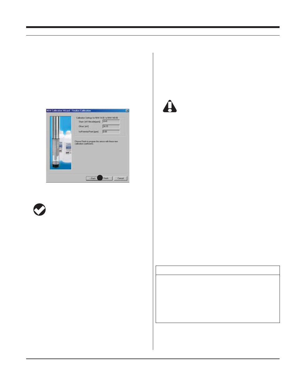
16. The final screen of the Calibration Wizard shows the sensor
slope and offset calculated during the calibration process. For a
three-point bithermal calibration, the calculated isopotential point
is shown. If a single-point calibration has been performed, the
isopotential point is the one calculated during the last three-point
bithermal calibration.
17. Select Finish to program the sensor with the newly calculated
calibration coefficients.
The ammonium sensor is now calibrated and ready to use.
TIP: You can look at the calibration report right after
calibrating, or at any time. See “Calibration History” in
Section 10 for details.
Options for storing sensors:
The ammonium sensor should calibrated immediately before use. If
storage is necessary, remove the sensor from the instrument and im-
merse in 14 ppm N solution, for later use in the low ammonium range,
or 140 ppm N solution, for use in the high range.
SENSOR SLOPE AND OFFSET
The expected slope for a new sensor is about 56 (± 2) mV per decade
of concentration (ppm). The calibration curve begins to deviate from
linear at about 1 ppm. The sensor’s zero offset is recalculated with
each single-point calibration.
UNITS AND CALCULATED MEASUREMENTS
Ammonium ion concentration is reported in ppm (equivalent to mg/L).
No calculated measurements are currently available.
USAGE RECOMMENDATIONS AND CAUTIONS
Ammonium Sensor
/PERATING
½#
Pressure Rating
20 psi (14 m, 46 ft)
pH range
up to 8.5
Do not submerge the ammonium sensor deeper than 46 ft
(14 m). Do not use in the basic pH range (8.5 or higher).
pH
The sensor’s pH range is that range over which a change in pH will
not cause a significant change in the measured voltage. It is the
plateau on a graph of pH against mV at constant concentration of the
detected ion. Outside this range, a change in pH may cause a signifi-
cant change in the measured mV.
TEMPERATURE
The higher the temperature, the shorter the lifetime of the electrode.
½#
CONDUCTIVITY
In saline waters (conductivities of 1,000 μS/cm or higher), the pres-
ence of interfering ions such as sodium or potassium may limit the
usability of the ammonium sensor.
POTENTIAL INTERFERENCES
The following table lists concentrations of possible interfering ions that
cause 10% error at various levels of NH
4
+
.
17
Ion
100 ppm NH
4
+
10 ppm NH
4
+
1 ppm NH
4
+
Cs
+
100
10 1
K
+
270
27
2.7
Tl
+
3100
310
31
H
+
pH 1.6
pH 2.6
pH 3.6
Ag
+
270,000
27,000
2700
Li
+
35,000
3500
350
Na
+
11,100
1,100
110
SECTION 15: AMMONIUM