In-Situ TROLL 9500 Operators Manual User Manual
Page 116
111
TROLL 9500 Operator’s Manual
0095110 rev. 007 01/09
2. Remove the sensor’s protective cap or storage bottle and set aside
for future storage of the sensor.
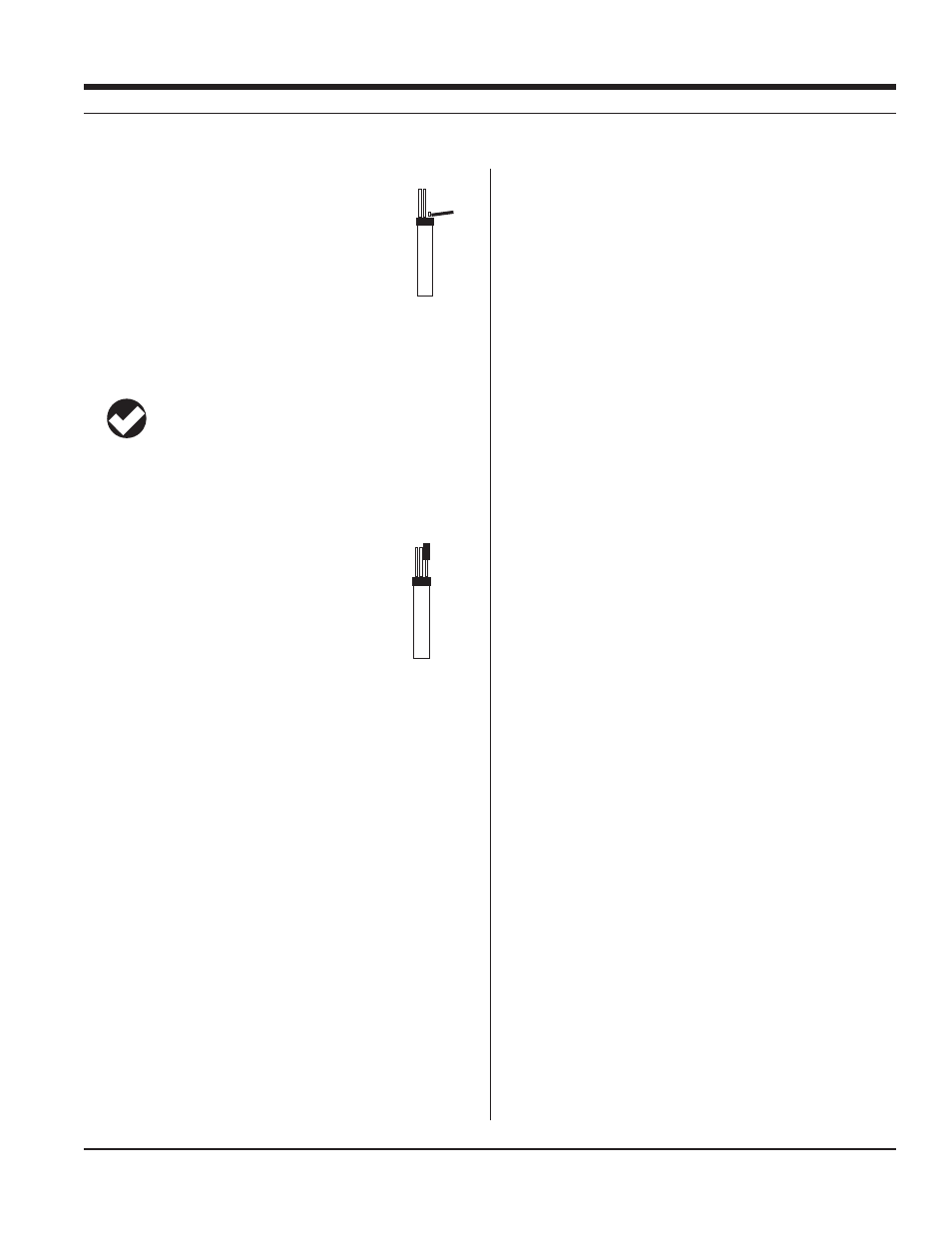
3. Remove any moisture or dirt from the area around
the port where you will install the sensor, then use the
sensor removal tool to remove the plug from the port
where you will install the sensor.
4. Remove any moisture or dirt from the port connector with a clean
swab or tissue.
5. Check lubrication of the sensor o-rings.
TIP: The sensor o-rings require generous lubrication before
installation. New sensors will be lubricated at the factory. If
the o-rings appear dry, apply apply a silicone lubricant before
installation.
6. Handling the sensor by the sides, not the tip, align the mark on the
side of the sensor with the mark on the port.
7. Use the sensor insertion tool to firmly press the
sensor into the port until you feel it dock with the
connector at the bottom. When properly inserted a
small gap (width of the sensor removal tool) remains
between the widest part of the sensor and the instru-
ment body, for ease of removal.
CALIBRATION
OVERVIEW
The software offers several options for chloride calibration.
s
two calibration points are taken in solutions of different concentra-
tions at the same temperature. The third point uses one of these
SOLUTIONS
s
tions of two different concentrations. A two-point isothermal calibra-
tion calculates the sensor’s slope and offset but cannot compute
the isopotential point. For best results this type of calibration should
be carried out as close as possible to the temperature at which the
sensor will be used. Or, it may be performed after a previous three-
point bithermal calibration to recalculate the slope and offset of an
aging sensor while retaining the previously calculated isopotential
point.
s
bration has established the sensor slope, offset, and isopotential
point, a single-point calibration may be used with good results to
adjust the offset on a daily basis.
CALIBRATION SOLUTIONS
Sodium chloride (NaCl) solutions certified to N.I.S.T. standards are
supplied in the In-Situ Chloride Calibration Kits:
35.5 ppm Cl
–
355 ppm Cl
–
3545 ppm Cl
–
Specialized calibration kits are available for calibrating the chloride
sensor for low-range and high-range measurements:
Low range: two quarts each 35.5 ppm and 355 ppm
High range: two quarts each 355 ppm and 3545 ppm
RECOMMENDED CALIBRATION FREQUENCY
Ion-selective electrodes are inherently unstable and drift is quite
normal. To achieve the most accurate sensor response, we recom-
mend a complete three-point bithermal calibration once a week, with a
single-point calibration daily or after 4-6 hours of use.
PREPARING TO CALIBRATE
You will need:
s
sensors or plugs in the other sensor ports
s
s
range you expect to measure. When performing a multi-point
calibration, begin with the lowest-concentration solution.
s
container of ice large enough to hold the Cal Cup (and stirrer, if
used).
s
field—for example, in stagnant or very slowly moving water. The
MORE
sensor
removal
tool
sensor
insertion
tool
SECTION 16: CHLORIDE