Probe compensation signal, Measurement, Press the utility key – GW Instek GDS-2000 series Uer manual User Manual
Page 53: Utility, Hori menu
MEASUREMENT
53
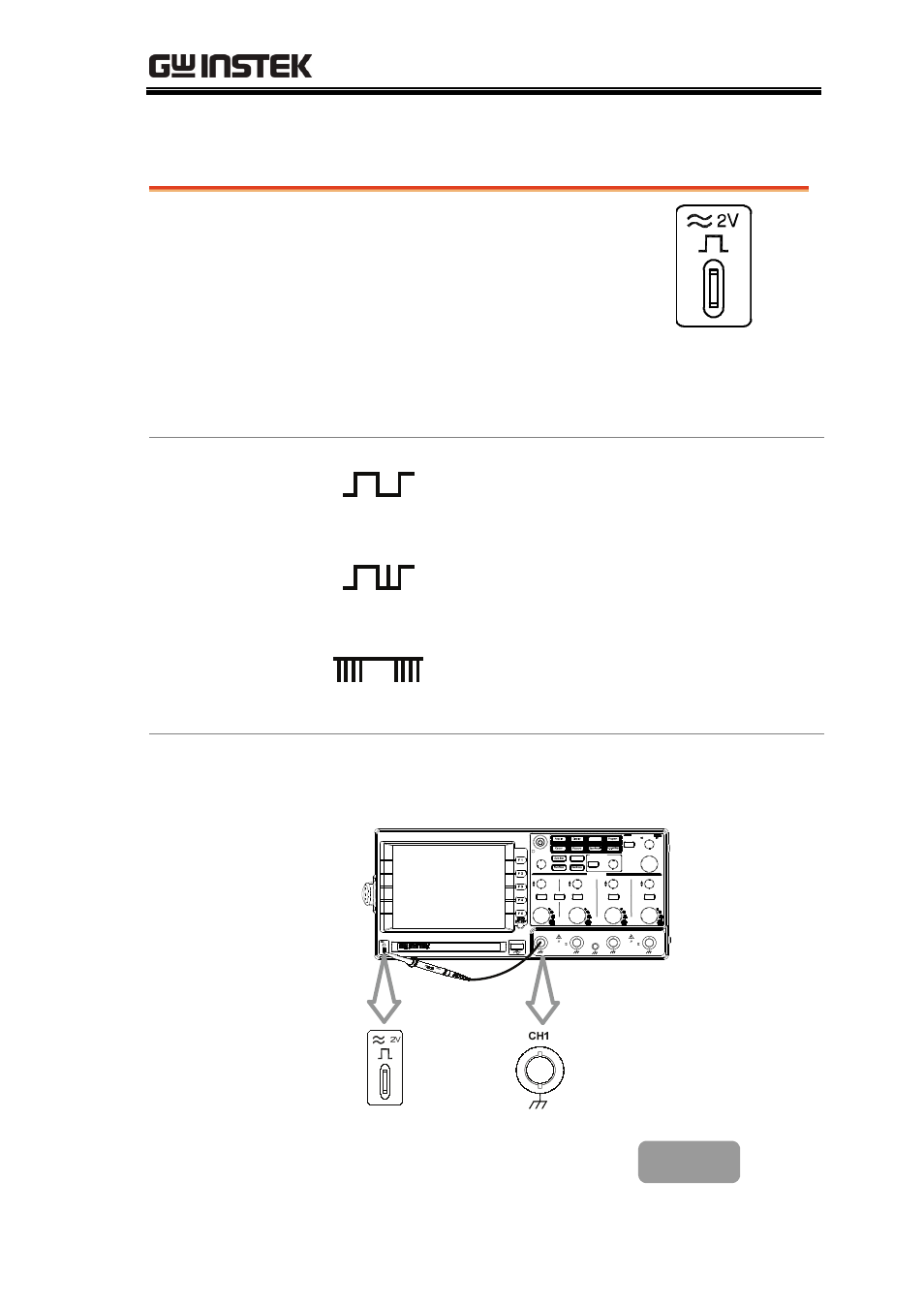
Probe compensation signal
Background
This section introduces how to use
the probe compensation signal for
general usage, in case the DUT
signal is not available. For probe
compensation details, see page159.
Note that the frequency accuracy and duty factor
are not guaranteed. Therefore the signal should
not be used for reference purpose.
Waveform type
Square waveform for probe
compensation. 1k ~ 100kHz, 5% ~
95%.
Demonstration signal to show the
effect of peak detection. See page85
for peak detection mode details.
Demonstration signal to show the
effect of long memory. See page87 for
memory length details.
View
compensation
waveform
1. Connect the probe between the compensation
signal output and Channel input.
Utility
Help
CH1
CH2
MATH
CH3
CH4
CH1
MENU
HORI
MENU
CH2
CH3
CH4
CAT
300V
M
16pF
MAX. 300Vpk
1
CAT
300V
M
16pF
MAX. 300Vpk
1
2V
POSITION
HORIZONTAL
TIME/DIV
LEVEL
TRIGGER
VARIABLE
STBY
ON/
POSITION
POSITION
POSITION
VERTICAL
POSITION
GDS-2104
Digital Storage Oscilloscope
100MHz 1G Sa/s
VOLTS/DIV
VOLTS/DIV
VOLTS/DIV
VOLTS/DIV
2. Press the Utility key.
Utility
- GDB-03 (99 pages)
- GLA-1000 Series User Manual (111 pages)
- GLA-1000 Series Quick start guide (20 pages)
- GOS-630FC (20 pages)
- GOS-635G (36 pages)
- GOS-6000 Series (27 pages)
- GOS-6103C (30 pages)
- GOS-6100 Series (30 pages)
- GRS-6000A Series (51 pages)
- GDS-122 Installation Guide (4 pages)
- GDS-122 User Manual (52 pages)
- GDS-2000A series CAN/LIN bus User Manual (18 pages)
- GDS-2000A series Quick start guide for DS2-FGN (6 pages)
- GDS-2000A series Freewave User Manual (26 pages)
- GDS-2000A series Quick start guide for Logic analyzer option (18 pages)
- GDS-2000A series Quick start quide for DS2-LAN (2 pages)
- GDS-2000A series Option User Manual (80 pages)
- GDS-2000A series User Manual (261 pages)
- GDS-2000A series Programming Manual (272 pages)
- GDS-2000A series Single sheet for LA Quick start guide (2 pages)
- GBS-1000 Series Programming Manual (88 pages)
- GBS-1000 Series User Manual (187 pages)
- GDS-1000-U Series firmware upgrade (1 page)
- GDS-1000-U Series Programming Manual (70 pages)
- GDS-1000-U Series Quick start guide (2 pages)
- GDS-1000-U Series User Manual (133 pages)
- GDS-1000A-U Series Programming Manual (88 pages)
- GDS-1000A-U Series Quick start guide (2 pages)
- GDS-1000A-U Series User Manual (148 pages)
- GDS-3000 Series GCP-530/1030 current probe User Manual (40 pages)
- GDS-3000 Series GDP-025/050/100 differential probe User Manual (21 pages)
- GDS-3000 Series DS3-PWR Power analysis manual (37 pages)
- GDS-3000 Series User Manual (209 pages)
- GDS-3000 Series Programming Manual (103 pages)
- GDS-3000 Series DS3-SBD Serial Bus decode (29 pages)
- GDS-3000 Series GKT-100 deskew fixture User Manual (1 page)
- GDS-3000 Series GUG-001, GPIB to USB adapter User Manual (15 pages)
- GDS-300 Series User Manual (188 pages)
- GDS-300 Series Programming Manual (139 pages)
- GDS-300 Series Quick start guide (21 pages)
- GRF-3300 Series Student Manual (26 pages)
- GRF-3300 Series Teacher Manual (26 pages)
- GRF-1300A (124 pages)
- GSP-810 User Manual (40 pages)
- GSP-810 Software Manual (3 pages)