Configuring the edge trigger – GW Instek GDS-1000-U Series User Manual User Manual
Page 87
CONFIGURATION
87
>
Longer than =
Equal to
<
Shorter than ≠
Not equal to
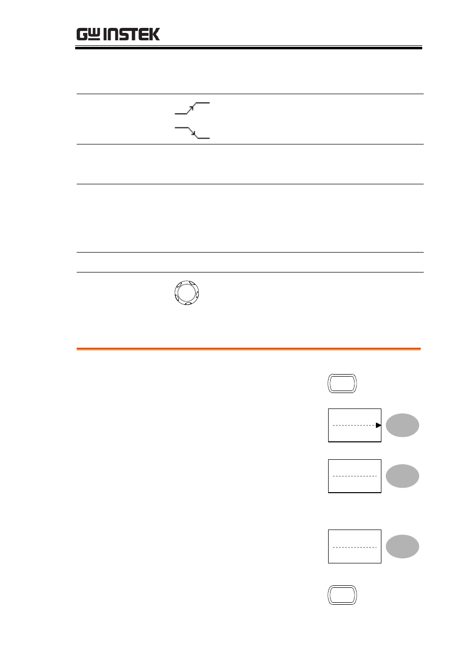
Trigger slope
Triggers on the rising edge.
Triggers on the falling edge.
Trigger coupling AC
Triggers only on AC component.
DC
Triggers on AC+DC component.
Frequency
rejection
LF
Puts a high-pass filter and rejects the
frequency below 50kHz.
HF
Puts a low-pass filter and rejects the
frequency above 50kHz.
Noise rejection
Rejects noise signals.
Trigger level
LEVEL
Using the trigger level knob moves the
trigger point up or down.
Configuring the edge trigger
Procedure
1. Press the Trigger menu key.
MENU
2. Press Type repeatedly to
select edge trigger.
Type
Edge
3. Press Source repeatedly to
select the trigger source.
Source
CH1
Range
Channel 1, 2, Line, Ext
4. Press Mode repeatedly to
select the Auto or Normal
trigger mode. To select the
single trigger mode, press
the Single key.
Mode
Auto
SINGLE
- GDB-03 (99 pages)
- GLA-1000 Series User Manual (111 pages)
- GLA-1000 Series Quick start guide (20 pages)
- GOS-630FC (20 pages)
- GOS-635G (36 pages)
- GOS-6000 Series (27 pages)
- GOS-6103C (30 pages)
- GOS-6100 Series (30 pages)
- GRS-6000A Series (51 pages)
- GDS-122 Installation Guide (4 pages)
- GDS-122 User Manual (52 pages)
- GDS-2000A series CAN/LIN bus User Manual (18 pages)
- GDS-2000A series Quick start guide for DS2-FGN (6 pages)
- GDS-2000A series Freewave User Manual (26 pages)
- GDS-2000A series Quick start guide for Logic analyzer option (18 pages)
- GDS-2000A series Quick start quide for DS2-LAN (2 pages)
- GDS-2000A series Option User Manual (80 pages)
- GDS-2000A series User Manual (261 pages)
- GDS-2000A series Programming Manual (272 pages)
- GDS-2000A series Single sheet for LA Quick start guide (2 pages)
- GBS-1000 Series Programming Manual (88 pages)
- GBS-1000 Series User Manual (187 pages)
- GDS-1000-U Series firmware upgrade (1 page)
- GDS-1000-U Series Programming Manual (70 pages)
- GDS-1000-U Series Quick start guide (2 pages)
- GDS-1000A-U Series Programming Manual (88 pages)
- GDS-1000A-U Series Quick start guide (2 pages)
- GDS-1000A-U Series User Manual (148 pages)
- GDS-3000 Series GCP-530/1030 current probe User Manual (40 pages)
- GDS-3000 Series GDP-025/050/100 differential probe User Manual (21 pages)
- GDS-3000 Series DS3-PWR Power analysis manual (37 pages)
- GDS-3000 Series User Manual (209 pages)
- GDS-3000 Series Programming Manual (103 pages)
- GDS-3000 Series DS3-SBD Serial Bus decode (29 pages)
- GDS-3000 Series GKT-100 deskew fixture User Manual (1 page)
- GDS-3000 Series GUG-001, GPIB to USB adapter User Manual (15 pages)
- GDS-300 Series User Manual (188 pages)
- GDS-300 Series Programming Manual (139 pages)
- GDS-300 Series Quick start guide (21 pages)
- GRF-3300 Series Student Manual (26 pages)
- GRF-3300 Series Teacher Manual (26 pages)
- GRF-1300A (124 pages)
- GSP-810 User Manual (40 pages)
- GSP-810 Software Manual (3 pages)