Gds-1000-u series user manual – GW Instek GDS-1000-U Series User Manual User Manual
Page 22
GDS-1000-U Series User Manual
22
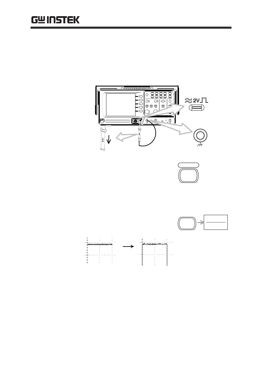
6. Connect the probe between the Channel1 input
terminal and probe compensation signal output
(2Vp-p, 1kHz square wave).
7. Set the probe attenuation voltage to x10.
VOLTS/DIV
VOLTS/DIV
TIME/DIV
CH 1
MATH
CH 2
MENU
MENU
Acquire
Display
Utility
Help
Run/Stop
VARIABLE
FORCE
Autoset
Cursor
SINGLE
Hardcopy
Measure
Save/Recall
LEVEL
VERTICAL
HORIZONTAL
TRIGGER
CH1
CAT
300V
M
W
15pF
MAX. 300Vpk
1
CH2
EXT TRIG
CAT
300V
M
W
15pF
MAX. 300Vpk
1
X
Y
X
1
0
X
1
CH1
x1
x10
8. Press the Autoset key. A
square waveform will
appear in the center of the
display. For details on
Autoset, see page 46.
Autoset
9. Press the Display key, then
Type and select the vector
waveform type.
Type
Vectors
Display
See also other documents in the category GW Instek Equipment:
- GDB-03 (99 pages)
- GLA-1000 Series User Manual (111 pages)
- GLA-1000 Series Quick start guide (20 pages)
- GOS-630FC (20 pages)
- GOS-635G (36 pages)
- GOS-6000 Series (27 pages)
- GOS-6103C (30 pages)
- GOS-6100 Series (30 pages)
- GRS-6000A Series (51 pages)
- GDS-122 Installation Guide (4 pages)
- GDS-122 User Manual (52 pages)
- GDS-2000A series CAN/LIN bus User Manual (18 pages)
- GDS-2000A series Quick start guide for DS2-FGN (6 pages)
- GDS-2000A series Freewave User Manual (26 pages)
- GDS-2000A series Quick start guide for Logic analyzer option (18 pages)
- GDS-2000A series Quick start quide for DS2-LAN (2 pages)
- GDS-2000A series Option User Manual (80 pages)
- GDS-2000A series User Manual (261 pages)
- GDS-2000A series Programming Manual (272 pages)
- GDS-2000A series Single sheet for LA Quick start guide (2 pages)
- GBS-1000 Series Programming Manual (88 pages)
- GBS-1000 Series User Manual (187 pages)
- GDS-1000-U Series firmware upgrade (1 page)
- GDS-1000-U Series Programming Manual (70 pages)
- GDS-1000-U Series Quick start guide (2 pages)
- GDS-1000A-U Series Programming Manual (88 pages)
- GDS-1000A-U Series Quick start guide (2 pages)
- GDS-1000A-U Series User Manual (148 pages)
- GDS-3000 Series GCP-530/1030 current probe User Manual (40 pages)
- GDS-3000 Series GDP-025/050/100 differential probe User Manual (21 pages)
- GDS-3000 Series DS3-PWR Power analysis manual (37 pages)
- GDS-3000 Series User Manual (209 pages)
- GDS-3000 Series Programming Manual (103 pages)
- GDS-3000 Series DS3-SBD Serial Bus decode (29 pages)
- GDS-3000 Series GKT-100 deskew fixture User Manual (1 page)
- GDS-3000 Series GUG-001, GPIB to USB adapter User Manual (15 pages)
- GDS-300 Series User Manual (188 pages)
- GDS-300 Series Programming Manual (139 pages)
- GDS-300 Series Quick start guide (21 pages)
- GRF-3300 Series Student Manual (26 pages)
- GRF-3300 Series Teacher Manual (26 pages)
- GRF-1300A (124 pages)
- GSP-810 User Manual (40 pages)
- GSP-810 Software Manual (3 pages)