3 home display, main display and monitor display, Home display, main display and monitor display -4, Nconfigure sensor – Yokogawa 2-Wire Dual Channel Transmitter/Analyzer FLXA21 User Manual
Page 84: Ntemperature settings, Nma (output)
<6. OPERATION OF SC (Conductivity)>
6-4
IM 12A01A02-01E
5th Edition : Oct. 31, 2013-00
n
Configure sensor
From among the sensor types displayed on this screen, select an appropriate electrode for the
sensor used. The measurement units can also be selected from among “/cm” and “/m”.
The cell constant (factory default) is determined by factory calibration made during
manufacturing.
The cell constant is indicated on the sensor. If a new sensor is used, the cell constant indicated
here should be changed. When this value is changed, the real cell constant will also be changed.
For details, see section 7.1.2.
n
Temperature settings
Select a suitable temperature element from among those displayed and set it up.
Celsius (ºC) or Fahrenheit (ºF) temperature scale can be selected.
For details, see section 7.1.3.
n
mA (output)
Select an appropriate process parameter from among those displayed and set it. The mA output
has been set to 0 – 500 µS/cm or 0 to 20 Ω cm at factory shipment. If a high resolution is required
in a consistent measurement process, set this parameter to a value suitable for the process.
For details, see section 7.2.
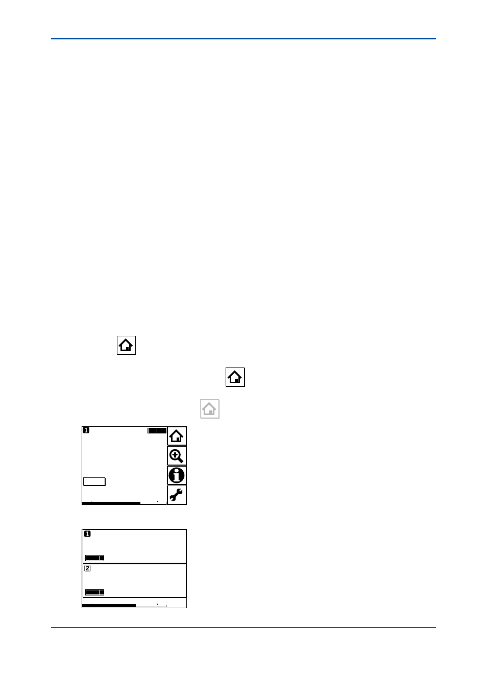
6.3
Home display, Main display and Monitor
display
Pressing
changes the screen to the Main display shown in Figure 6.3 (or the Home display
shown in Figure 6.4).
If two sensors are connected, pressing
on the Main display changes the display to the
Home display shown in Figure 6.4.
If only one sensor is connected,
is grayed out and disabled on the Main display.
10.38
Tag:FLXA21–SC
25.0
4mA
20mA
Conduct1-TC1
°C
mS/cm
Figure 6.3
Example of main display
6.35
Tag:FLXA21–SC
24.9
4mA
20mA
Conduct1-TC1
°C
mS/cm
Tag:FLXA21–SC
25.0 °C
mS/cm
10.38
Figure 6.4
Example of home display