2 wiring the conductivity (sc) sensor, 3 wiring the inductive conductivity (isc) sensor, Wiring the conductivity (sc) sensor -12 – Yokogawa 2-Wire Dual Channel Transmitter/Analyzer FLXA21 User Manual
Page 39: Wiring the inductive conductivity (isc) sensor -12
<2. WIRING AND INSTALLATION>
2-12
IM 12A01A02-01E
5th Edition : Oct. 31, 2013-00
2.5.2
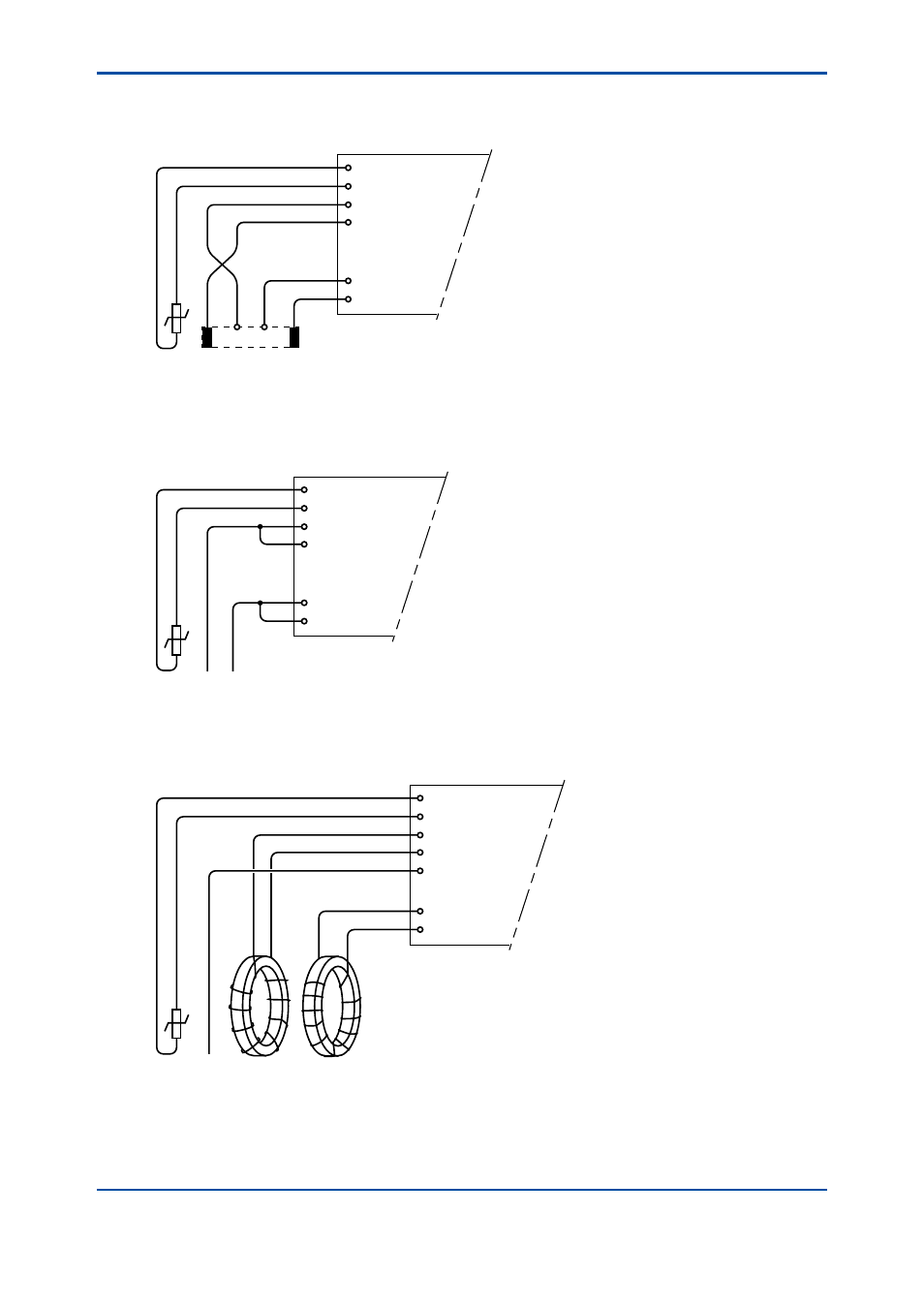
Wiring the conductivity (SC) sensor
Contacting Conductivity, SC, sensors are connected to the module as follows:
11 +
-
V-
i-
Temp
V+
i+
12
13
14
15
16
The above diagram shows wiring for 4-electrode conductivity sensors, such as SC42-SP34
large bore series. For 2-electrode conductivity sensors, such as SC42-SP36 small bore series,
jumpers must be installed between terminals 13-14 and between terminals 15-16, as shown in
the diagram below.
11 +
-
V-
i-
Temp
V+
i+
12
13
14
15
16
2.5.3
Wiring the inductive conductivity (ISC) sensor
ISC40 sensors are connected to the module as follows:
11 +
-
Temp
Receive coil
Drive coil
12
13
17
15
16
14
shield
Sensor shield
(internal)
shield
The sensors are supplied with integral cables and each individual wire is marked with the
corresponding terminal numbers.