2 connection of the power supply, 3 wiring cover, Connection of the power supply -6 – Yokogawa 2-Wire Dual Channel Transmitter/Analyzer FLXA21 User Manual
Page 33: Wiring cover -6, Caution
<2. WIRING AND INSTALLATION>
2-6
IM 12A01A02-01E
5th Edition : Oct. 31, 2013-00
l
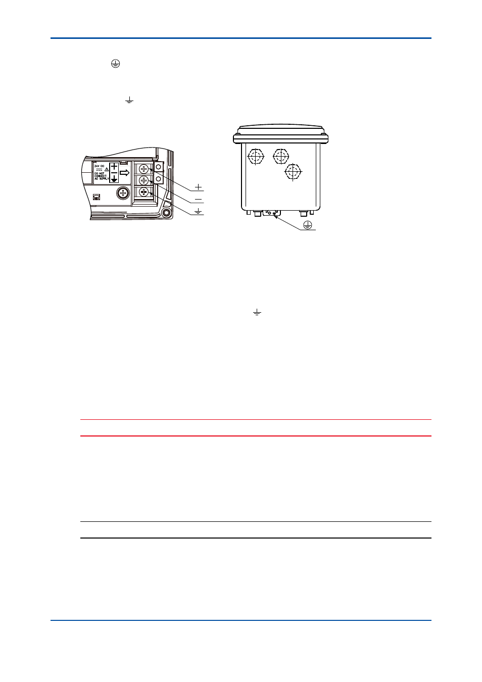
Grounding the stainless steel housing
Use the terminal outside the converter housing for grounding (Figure 2.7B).
Use a ring terminal.
When connecting the converter to a distributor, connect the shield of a double-core shielded
cable to the terminal on the terminal block in the converter. Do not connect the shield to the
ground terminal in the distributor.
A: Plastic housing
(Internal grounding)
B: Stainless steel housing
(External grounding)
Figure 2.7
Grounding
2.4.2
Connection of the power supply
Pass the supply/output cable through the power cable hole shown in Figure 2.3 into the converter
and connect it to the terminals marked +, – and according to the marks on the power terminal
(Figure 2.7A).
2.4.3
Wiring cover
After grounding and connecting the power supply, check the wiring and then close the wiring
cover 3 (Figure 2.2).
When closing the cover, engage the positions marked with ○ in Figure 2.2 and fasten the cover
with the screw at the position marked with ∆.
CAUTION
The screw in the area marked with ∆ should be tightened to a torque of 0.35 to 0.45 N•m.
If a second module is used, wire the sensor for the second module and attach the wiring cover
(refer to figure 2.8).
Then, wire the sensor for the first module and attach the wiring cover (refer to figure 2.9).
The sensor wiring is shown in section 2.4.
NOTE
Be careful not to lose the wiring cover screws.