Supplement, User’s manual, Supplement model flxa21 2-wire analyzer – Yokogawa 2-Wire Dual Channel Transmitter/Analyzer FLXA21 User Manual
Page 244: Ninstructions related to nepsi type is added
User’s
Manual
All Rights Reserved. Copyright © 2013, 1st Edition: Nov. 27, 2013 (YK)
Supplement
Model FLXA21
2-Wire Analyzer
IM 12A01A02-01E 1/3
5th Edition
Thank you for selecting our FLXA21 2-Wire Analyzer.
Though User’s Manual, IM 12A01A02-01E 5th Edition, is provided with the product, an addition to
the manual has been made.
Please attach a copy of this supplement to the manual and follow the instructions below when
using the instrument.
Note
n
Instructions related to NEPSI type is added.
Model FLXA21 2-Wire analyzer has been certified as explosion proof equipment by NEPSI.
Information and instructions related to NEPSI certification is added to the manual.
l
Section 1.4 Regulatory Compliance
The followings are added to the article.
Explosion-proof (Intrinsically safe type and non-incendive) (for suffix code: -EA):
NEPSI Intrinsically safe approval
Applicable standard
GB 3836.1-2010 Explosive atmospheres-Part 1: Equipment - General requirements
GB 3836.4-2010 Explosive atmospheres-Part 4: Equipment protection by intrinsic safety “i”
GB 3836.20-2010 Explosive atmospheres-Part 20: Equipment with equipment protection level (EPL)
Ga
Type of protection
Ex ia IIC Ga
T4: for ambient temperature: -20°C to 55°C
T6: for ambient temperature: -20°C to 40°C
Atmosphere pressure: 80kPa (0.8bar) to 110kPa (1.1bar)
Degree of Protection of the Enclosure: IP66
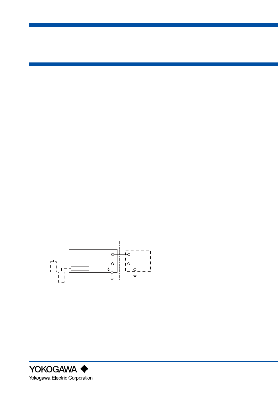
Control Drawing (NEPSI types)
Measuring module 1
Note: The measuring module on this drawing means
the sensor module on this General Specifications.
Measuring module 2
Sensor 1
Sensor 2
(*)
(Note 1)
Safety Barrier
Housing Assembly
Supply -
Supply +
→
Non Hazardous Location
Hazardous Location
←
-
+
Electrical data are as follows;
Maximum Voltage (Ui) = 30V
Maximum Current (Ii) = 100mA
Maximum Power (Pi) = 0.75W
Internal Capacitance (Ci) = 13F
Internal Inductance (Li) = 0mH
Note 1: The output current must be limited by a resistor “R” such that Imaxout=Uz/R (linear source).
Note 2: Safety barrier certified by NEPSI should be used.
Note 3: When using non isolation barrier, connect (*) to IS earthing system.
Note 4: Sensor module 2 is installed when required.
When measuring inductive conductivity, only one module can be installed.