App.2-12, Nchanging the settings – Yokogawa 2-Wire Dual Channel Transmitter/Analyzer FLXA21 User Manual
Page 228
App.2-12
IM 12A01A02-01E
5th Edition : Oct. 31, 2013-00
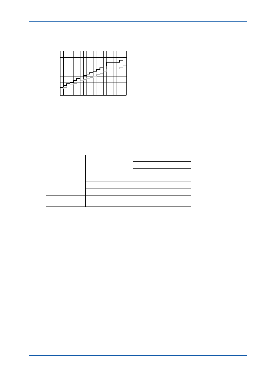
The USP<645> limit value is a non-temperature-compensated conductivity. When a measuring
conductivity needs to be shown on the main or home display as a non-temperature-compensated
conductivity, set the temperature compensation on “None”. (Refer to the section 7.1.4.)
0.0
0.5
1.0
1.5
2.0
2.5
3.0
3.5
25
50
75
100
USP safety margin
(user programmable)
USP limit
Temperature (°C)
Conductivity (µS/cm)
Figure 3 Conductivity limit value and temperature directed by USP<645>
n
Changing the settings
If any setting is accidentally changed, values to the right of the relevant arrow in Table 6 are all
initialized.
Table 6 Parameters that initialize other values
Measurement ->
Output: Process
parameter ->
Linear: 0% value, 100% value
Table
Communication: HART: PV
Display setup: Individual display (Main display)
Trend Graph Screen ->
Y-axis (low, high)
Communication: HART
Configure sensor:
Measuuring unit ->
Display setup: Individual display (Main display): unit