3 installing the cable glands, Installing the cable glands -3, Caution – Yokogawa 2-Wire Dual Channel Transmitter/Analyzer FLXA21 User Manual
Page 30: Ph sc isc do, Sencom
<2. WIRING AND INSTALLATION>
2-3
IM 12A01A02-01E
5th Edition : Oct. 31, 2013-00
2.3
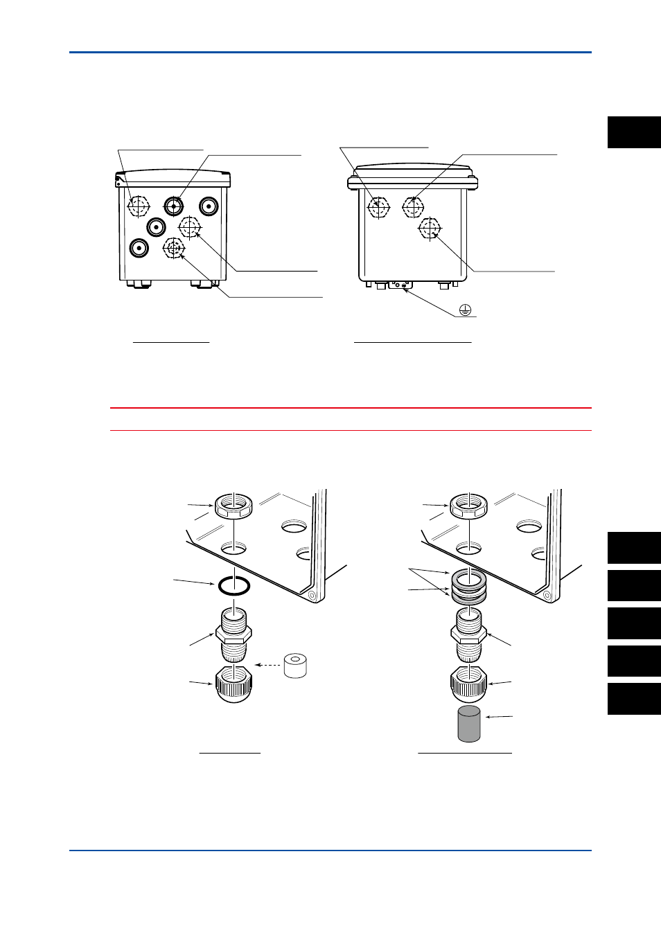
Installing the cable glands
The supplied cable glands are for cables with an outside diameter of 6 to 12 mm (0.24 to 0.47
inches). Unused cable entry holes must be sealed with cable glands including the supplied close
up plugs.
(A hole is drilled, if specified.)
Plastic Housing
Stainless Steel Housing
(For sensor 2 cable)
For sensor 1 cable
(For sensor 2 cable)
For sensor 1 cable
For power supply
For power supply
For grounding cable
F0202.ai
Figure 2.3
Cable gland diagram
CAUTION
Be careful not to be injured by the sharp hole edges on the housing.
Install the supplied cable gland as shown in Figure 2.4. When using an adapter for conduit work,
see Figure 2.5.
F0203.ai
Cable gland nut
O-ring
Gable gland
Sleeve
(for grounding cable line
of the plastic housing)
Plastic Housing
Cable gland cap
Cable gland nut
Gaskets
Washer
Stainless Steel Housing
Gable gland
Cable gland cap
Rubber plug
(without wiring)
Figure 2.4
Cable glands
The unused cable glands should be sealed with the supplied close up plug.
PH
SC
ISC
DO
SENCOM
2