1 wiring the ph/orp sensor, Wiring the ph/orp sensor -10, Nph measurement – Yokogawa 2-Wire Dual Channel Transmitter/Analyzer FLXA21 User Manual
Page 37
<2. WIRING AND INSTALLATION>
2-10
IM 12A01A02-01E
5th Edition : Oct. 31, 2013-00
2.5.1
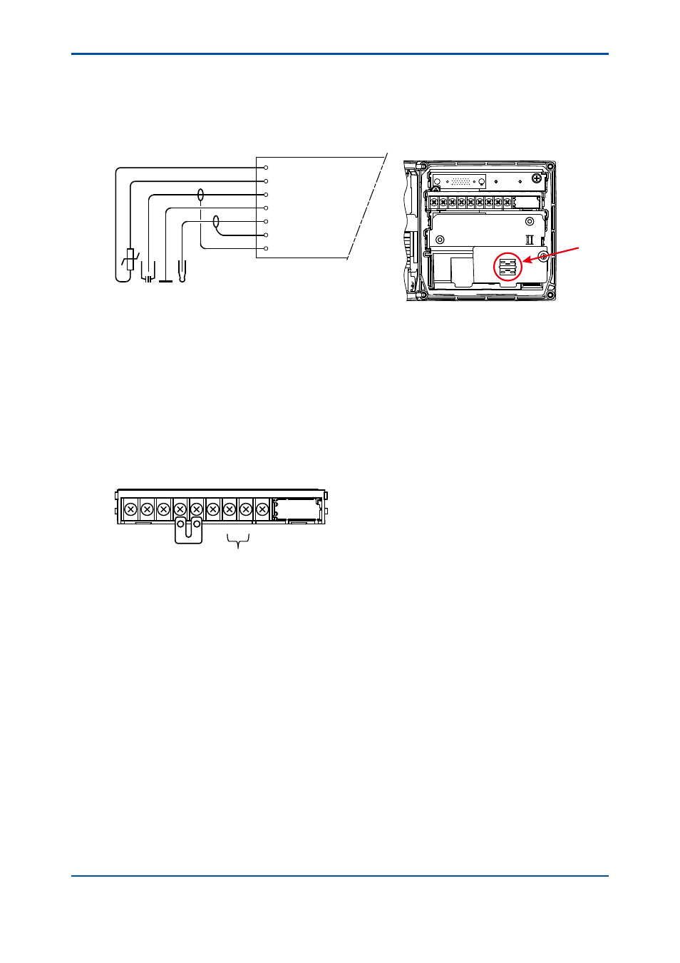
Wiring the pH/ORP sensor
n
pH Measurement
Conventional pH sensors are connected to the module as follows:
11 Temperature
12 Temperature
13 Reference
14 Solution ground
15 Glass (measure)
16 Shield
17 Shield
FLXA21
REF
TC
PH
Liquid
Earth
In addition to the wiring of the sensor, insure that a jumper for low-impedance sensor inputs is
installed. The jumpers can be found on the plastic sensor module cover and can be stored in the
lower level module wiring cover.
• pH Glass Electrode is a high impedance sensor input
• Standard reference electrodes and an ORP/REDOX electrode are low impedance sensor
inputs
• Special electrodes using 2 glass sensor (example: Pfaudler, SC24V) do not need jumpers.
Terminals 15-16 are identified as input 1 (High Impedance) and terminals 13-17 are defined as
input 2 (Low Impedance). For conventional pH sensors, the jumper is placed as illustrated:
16
15
19
17
13
18
14
12
11
PH
Input 1
Input 2
Glass sensor on Input 1.
Reference sensor on Input 2.