Yokogawa 2-Wire Dual Channel Transmitter/Analyzer FLXA21 User Manual
Page 185
<16. COMMISSIONING OF SENCOM pH/ORP>
16-2
IM 12A01A02-01E
5th Edition : Oct. 31, 2013-00
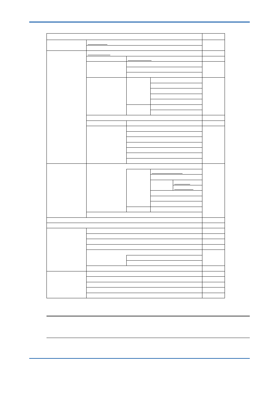
Table 16.1
Menu Structure and Default Values in “Commissioning”
Parameter
Ref. sect.
Sensor setup
Sensor type
16.1
Safe sensor disconnection
Measurement setup
Measurement
16.2.1
Temperature setting
Temp. element
16.2.2
Temp. compensation
Compensation
16.2.3
Reference temp.
Process Temp. Compensation
Calibration settings
pH settings
Zero and Slope units
16.2.4
Limits and timig
Buffers (select set)
Zero/Slope/ITP
Auto correct (Zero, Slope)
ORP settings
rH settings
Limit and timing
Zero/Slope
Impedance settings
16.2.5
Concentration
Unit
16.2.6
Sensor diag. settings
Input 1 imp.:
16.2.7
FINE
Input 2 imp.:
Process time
Heat cycle:
Define heat cycle
Define SENCOM status
Output setup
mA
16.3
Output
Process parameter
Setup
Linear
0 % value
100% value
Table
Burn
Damping time
Simulate
Simulation perc.
Configure Hold
Error configuration
16.4
Logbook configuration
16.5
Advanced setup
Settings
16.6.1
Tag
16.6.2
Passwords
16.6.3
Date/Time
16.6.4
Communication
16.6.5
HART
PH201G
Factory setup
16.6.6
Display setup
Main display
16.7.1
Trend
16.7.2
Auto Return
16.7.3
Adjust contrast
16.7.4
MONITOR display
16.7.5
NOTE
All the parameters for the quick setup (underlined ones in Table 16.1) are crucial for
measurement. If you change any of them, other parameters may be initialized. For the
parameters that may initialize other values, see Appendix 1.