Nmain display, 1ph sc isc do, Sencom – Yokogawa 2-Wire Dual Channel Transmitter/Analyzer FLXA21 User Manual
Page 17
<1. INTRODUCTION AND GENERAL DESCRIPTION>
1-5
IM 12A01A02-01E
5th Edition : Oct. 31, 2013-00
n
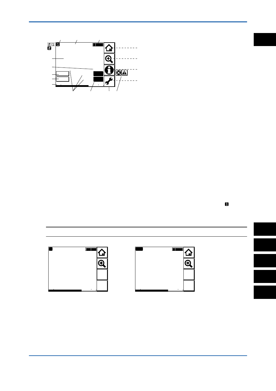
Main display
10.38
Tag:FLXA21–PH
TEXT_PH1
TEXT_ORP1
TEXT_TEMP1
19
25.0
mV
4mA
20mA
PH1
°C
pH
HOLD
WASH
Go to Home (Figure 1.6)
Go to Zoom (Figure 1.8)
Go to Infomation (Figure 1.10)
Go to Execute & Setup (Figure 1.11)
B
C
A
D
J
G
E
F
K
H
M
L
Figure 1.4
Example of main display
Main display
The Main display appears upon startup when one sensor is connected and the MONITOR
display is disabled.
A: Measurement value: Primary value (large characters/user selectable)
B, C: Measurement value: Second and tertiary values (small characters)
D: Unit for the primary value
E: Tag No. (user programmable)
F: Sensor No. *
G: Sensor wellness indicator (More ■ indicate the better condition.)
H: Hold/Wash indicators (appear only during the Hold/Wash operations)
J: Analog output display and parameter * (ex.: PH1…PH=Parameter, 1=sensor number)
K: Additional text (set in alphanumeric characters/user programmable)
L: Function buttons (Home, Zoom, Status, Execute & Setup)
M: Fault/Warning indicators (indicated in blinking only during Fault/Warning status)
* When the parameter of which measurement value is indicated is selected as a process
parameter, that is, mA output set on the Output setup (refer to the section 5.3, 8.2, 11.2, and
14.3), its Sensor No. is indicated as a white number in the black box, for example , and its
mA output is indicated as a bar at the bottom. At the bar, a parameter symbol is indicated.
NOTE
Measurement values on the display can be set independent of the process parameter.
0.03
4mA
20mA
Diff-pH
pH
C
Sensor
2
Sensor
1
Calculated data
Differential
10.38
4mA
20mA
PH1
pH
Sensor
2
Sensor
1
R
(
1
)
Redundant sys.
Figure 1.5
Example of calculated date and redundant system
1
PH
SC
ISC
DO
SENCOM