D3-37, Allocating backbone routers (bbr) – Yokogawa YFGW410 User Manual
Page 98
D3-37
IM 01W02D01-01EN
Six types of icons are displayed at the bottom of the main window.
Icons and operations scope
Icon
Name
Operation scope
YFGW410
Indicates a YFGW410. It cannot be allocated in the backgroud image area.
Backbone Router
Indicates a Field Wireless Access Point with a backbone router role. Al-
locate registered devices on the backgroud image area.
Routing Device
Indicates devices with Router or IO+Router roles. Allocate registered de-
vices on the backgroud image area.
IO Device
Indicates devices with IO or IO(Auto) roles only. Allocate registered devices
on the backgroud image area.
Device Group
Indicates groups of IO devices with the same connection device on the host
side. Allocate registered groups on the backgroud image area.
A
Comment
Add a comment to the backgroud image area.
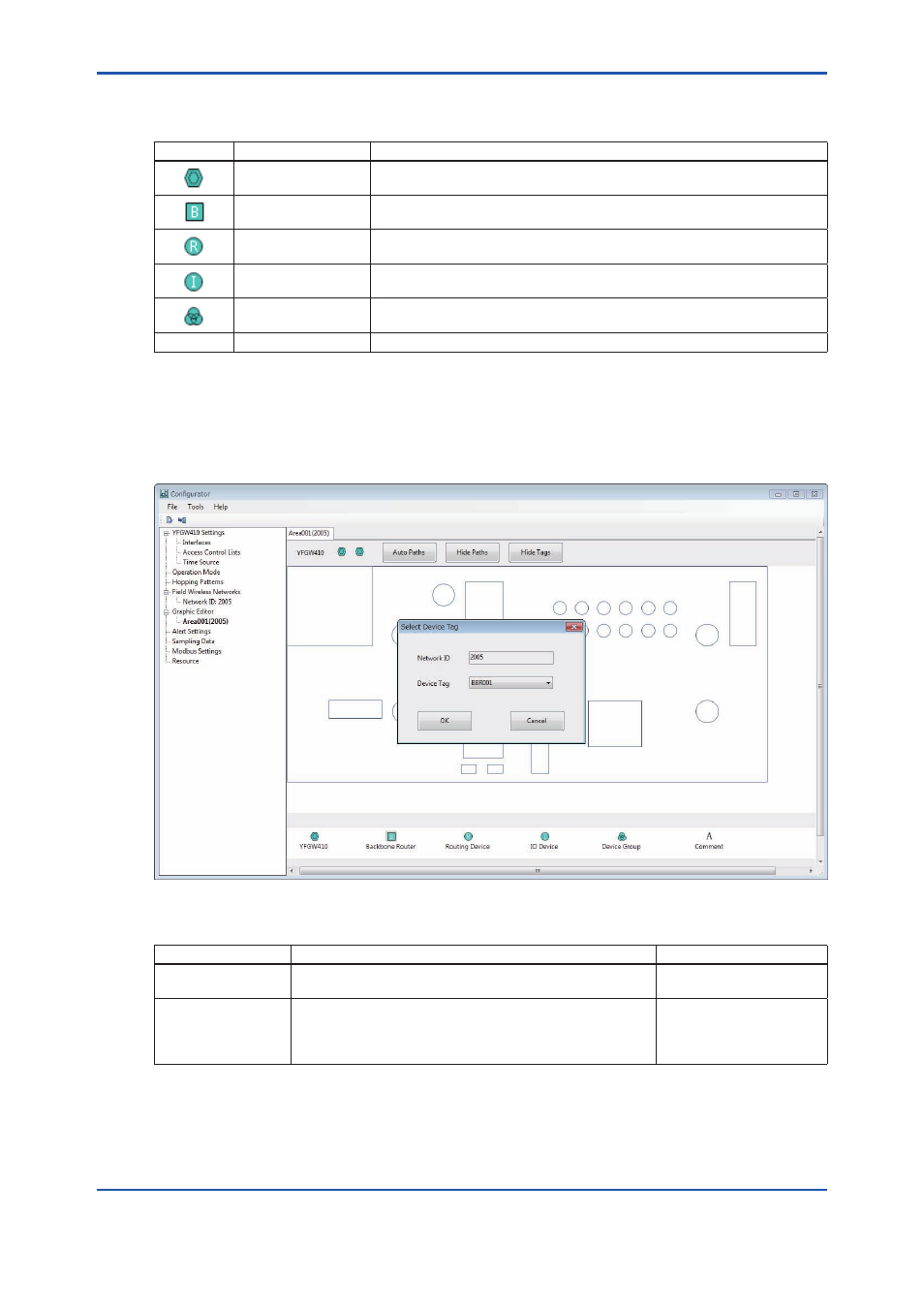
Allocating Backbone Routers (BBR)
To allocate a backbone router, drag and drop the backbone router icon at the bottom of the main
window to the allocation position on the background image area. The shown in Figure D3-36 ap-
pears. Select the device tag of the device to be allocated.
FD0336.ai
Figure D3-36 Select Device Tag Window
Item
Description
Default setting
Network ID
Automatically displays the network ID set for the area
displayed.
Automatically displayed
Device Tag
The device tags of backbone devices registered with the
relevant network ID are displayed in the drop-down box.
Select the device tag of the wireless device to be allocated
at the position.
Displays registered unal-
located devices in ascend-
ing order
When the [OK] button is clicked, the icon of the device and the device tag appear in the specified
position, as shown in Figure D3-37. When the [Cancel] button is clicked, the settings are discard-
ed and nothing is added to the backgroud image area.