C4-10, Important, Nmaintenance interface – Yokogawa YFGW410 User Manual
Page 48: Nsynchronization connector
C4-10
IM 01W02D01-01EN
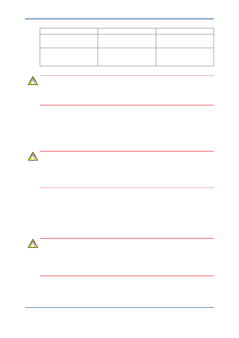
Table C4-2 Modbus/RTU Communication Parameters of YFGW410
Item
Description
Note
Serial Communication
Boat rate: 38.4kbps
Parity: Even
Stop bit: 1 bit
Fixed values
Modbus/RTU
Modbus Slave
Modbus/RTU Address: 1
Configure the host system as Mod-
bus Master.
Modbus/RTU address of the host
system should be except 1.
IMPORTANT
Modbus/RTU supports to access up to 125 words at once. However, part of information may not
be accessed through Modbus/RTU, because number of accessible words depended on a Mod-
bus/RTU client. For details, see users’ manual of the host system.
n
Maintenance interface
Connect the 100BASE-TX compliance cable, terminated with an RJ-45 connector, to the main-
tenance interface (M1) on the front panel of the YFGW410. Connect the Field Wireless Manage-
ment Console to this port for configuration of a field wireless network and the YFGW410.
IMPORTANT
When CENTUM VP is running, set and adjust the parameters of the field wireless device from
PRM.
When CENTUM VP is not running, or when a non-Yokogawa host system is connected, the pa-
rameters can be set and adjusted using FieldMate.
n
Synchronization connector
In order to build redundancy YFGW410, connect an attached cable for redundancy to the syn-
chronization connector in the front of YFGW410. When using single YFGW410, connect the
terminator to the synchronization connector. If nothing has connected with a synchronization con-
nector, YFGW410 does not operate.
IMPORTANT
• The cable for redundancy has the D-sub 15-pin connector at both ends. Secure the cable
connector to the synchronization connector using screws. When cables other than an at-
tached cable for redundancy are connected, these operation is not guaranteed.
• If nothing has connected with a synchronization connector, YFGW410 does not operate.