D3-62, For data type mapping, Batch operation – Yokogawa YFGW410 User Manual
Page 123
D3-62
IM 01W02D01-01EN
The list is comprised of a column of registers numbers starting from 0 and a column of parameter
names.
Areas in which process values are allocated are light blue and areas in which statuses are al-
located are light pink. The first row of the addresses contains the parameter name.
For Data Type Mapping
The status and value of the parameters which send to a host system are separated and mapped
to respective areas.
When Data Type Mapping is selected at the [Modbus Settings] tab, parameter values are al-
located to register numbers lower than the start status registers. The status of parameters are
automatically arranged in accordance with the following rule after a start of status registers. The
status of parameters are allocated in order which has arranged the value in the status allocation
range for every value data size.
When [Start of status registers] is 20000 (devices with 65536 registers)
Value data size
Status allocation range
8 words
20000~29999
2 words
30000~39999
1 word
40000~59999
When [Start of status registers] is 5000 (devices with 10000 registers)
Value size
Status allocation range
8 words
5000~5999
2 words
6000~8999
1 word
9000~13999
Example) When the data value is two words ([Start of status registers] is 5000)
Top number of value
Status allocation number
0
6000
2
6001
4
6002
• • •
• • •
500
6250
502
6251
Batch Operation
There is a [Batch Operation] button at the bottom of the [Input Registers] tab
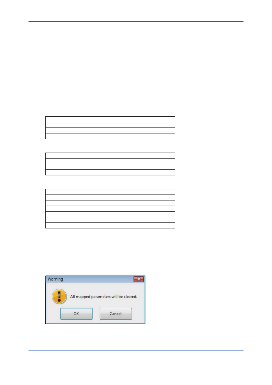
When the [Auto Mapping] button is clicked, all parameters are automatically allocated. When
data has been already allocated, all allocation information is discarded and allocation is per-
formed again. The dialog shown in Figure D3-62 appears.
FD0368.ai
Figure D3-62 Warinig Dialog