Figure 3-14: pc415c panel cutout dimensions, Figure 3-15: pc417c panel cutout dimensions, Figure 3-16: pc419c panel cutout dimensions – Maple Systems PC419C User Manual
Page 47: 565h, Figure 3-13, 5 66h, Figure 3-14 and, 5 67h, Figure 3-15 )
Page 35
1010-1023, Rev 00
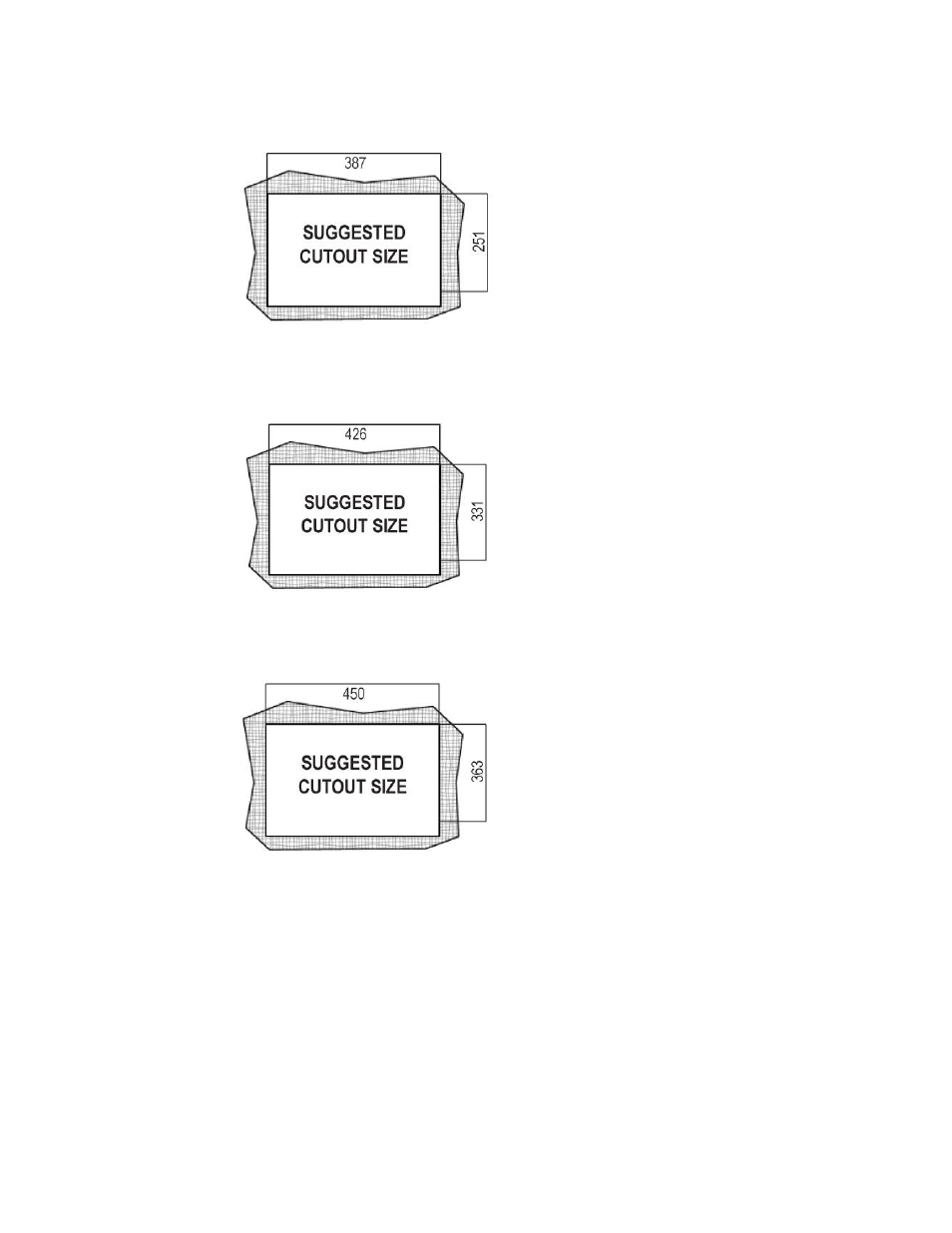
Figure 3-13: PC415C Panel Cutout Dimensions
Figure 3-14: PC417C Panel Cutout Dimensions
Figure 3-15:
PC419C Panel Cutout Dimensions
Step 3:
Slide the PC400C Series Panel PC through the hole until the metal frame is
flush against the panel.
Step 4:
Insert the panel mounting clamps into the pre-formed holes along the edges of
the PC400C Series Panel PC, behind the aluminum frame (
Figure 3-16). Refer
to the mounting kit packing list for the required number of mounting clamps.