1 +12v power source connector (cpu12v1), 2 atx power connector (atx1), Table 6-1: peripheral interface connectors – Maple Systems PC419C User Manual
Page 111: Table 6-3: atx power connector (atx1) pinouts
Page 99
1010-1023, Rev 00
Connector
Type
Label
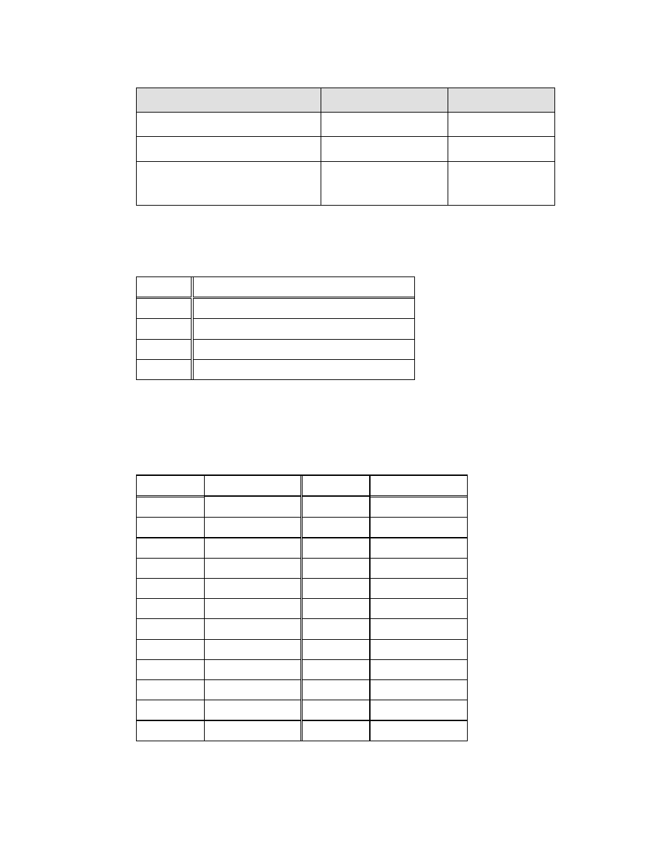
SPI Flash connector
8-pin header
JSPI1
Touch panel connector
9-pin wafer
TOUCH1
USB 2.0 connectors
8-pin header
USB1, USB2,
USB3, USB4
Table 6-1: Peripheral Interface Connectors
6.2.1 +12V Power Source Connector (CPU12V1)
6.2.2 ATX Power Connector (ATX1)
PIN NO.
DESCRIPTION
PIN NO.
DESCRIPTION
1
+3.3V
13
+3.3V
2
+3.3V
14
-12V
3
GND
15
GND
4
+5V
16
PS_ON-
5
GND
17
GND
6
+5V
18
GND
7
GND
19
GND
8
NC
20
NC
9
+5V
21
+5V
10
+12V
22
+5V
11
+12V
23
+5V
12
+3.3V
24
GND
PIN NO.
DESCRIPTION
1
GND
2
GND
3
+12V
4
+12V
Table 6-2: +12V Power Source Connector ( CPU12V1) Pinouts
Table 6-3: ATX Power Connector (ATX1) Pinouts