Lincoln Electric IM10178 POWER FEED 84 U.I. CONTROL BOX User Manual
Page 37
B-1
OPERATION
The serviceability of a product or structure utilizing the
welding programs is and must be the sole responsibility of
the builder/user. Many variables beyond the control of The
Lincoln Electric Company affect the results obtained in
applying these programs. These variables include, but are not
limited to, welding procedure, plate chemistry and
temperature, weldment design, fabrication methods and
service requirements. The available range of a welding
program may not be suitable for all applications, and the
build/user is and must be solely responsible for welding
program selection.
poWer up seQuence
1. The contactor drive energizes the contactor to match the
active wire drive. The LED for the active wire drive
illuminates.
2. Settings of the feeder before the last power-down are
restored – wire feed speed, voltage, trigger type,
procedure, etc.
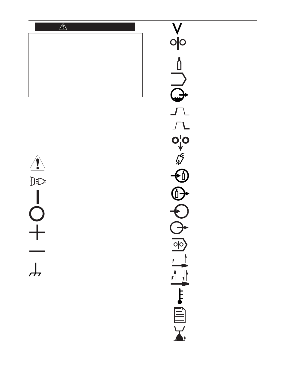
POWER FEED 84, POWER FEED 84 DUAL
ON
OFF
WIRE FEEDER
SHIELDING GAS
MENU
WAVE CONTROL
ARC END
PARMETERS
ARC START
PARMETERS
COLD FEED
GAS PURGE
SHIELDING GAS
INLET
SHIELDING GAS
OUTLET
M
MEMORy SAVED
M
MEMORy RECALL
WIRE DRIVE
SELECTION
2-STEP TRIGGER
4-STEP TRIGGER
THERMAL
SET-UP MENU
TRIM
WELDING AMPERAGE
WELDING VOLTAGE
POSITIVE OUTPUT
NEGATIVE OUTPUT
INPUT POWER
INPUT VOLTAGE
INPUT CURRENT
OUTPUT CURRENT
CHASSIE GROUND
WARNING OR
CAUTION
U1
I1
I2
A
graphic sYMbols ThaT appear on poWer feed 84,
poWer feed 84 dual or in This Manual
WARNING