Lincoln Electric IM10178 POWER FEED 84 U.I. CONTROL BOX User Manual
Page 19
A-12
INSTALLATION
POWER FEED 84, POWER FEED 84 DUAL
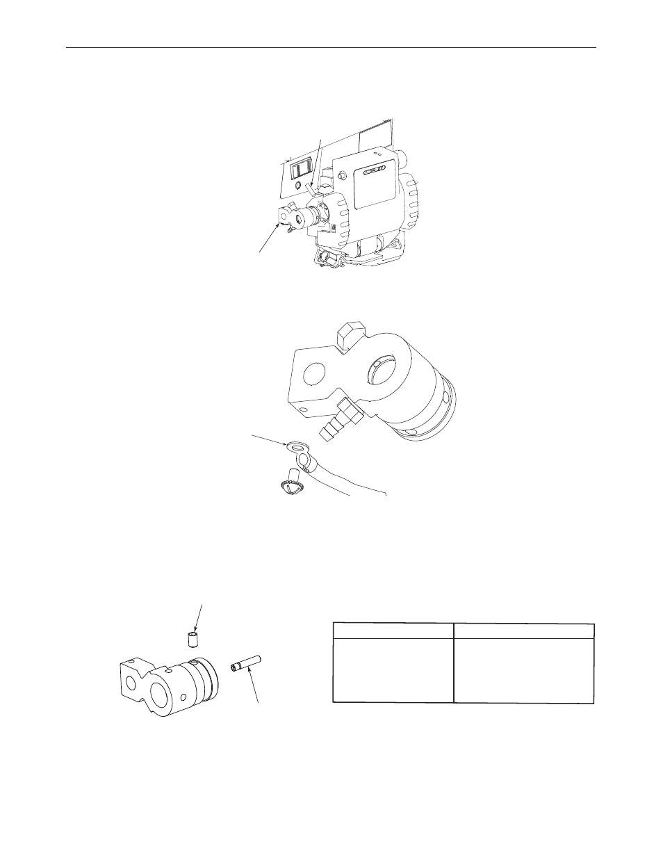
4. Use a 1/8” hex key to loosen the set screw securing the gun
adapter.
5. Remove the sense lead with a Phillips screw driver.
6. If a gas hose is attached to the gun adapter, use pliers to remove
the hose clamp and remove the gas hose.
7. If the gun adapter requires guide tubes, install the correct size
guide tube and secure with the set screw.
8. Assemble the sense lead to the new gun adapter. Orient the lead
towards the rear of the gun adapter.
9. If required, assemble the gas hose to the gun adapter or the fitting
on the feed plate and secure with a hose clamp.
10. Assemble the gun adapter to the wire drive. Tighten the set
screw once the gun adapter is at a 90° angle.
Wire size
Number of grooves in guide tube
.023-.045” ( 0.6 – 1.2mm)
1
.045 – 1/16” (1.2 – 1.6 mm)
2
1/16 – 5/64” (1.6 – 2.0 mm)
3
.068 – 7/64” (2.0 – 2.8 mm)
4
SET SCREW
GUN ADAPTER
SENSE
LEAD
Figure a.13
Figure a.14
Figure a.15
SET SCREW
GUIDE TUBE