Lincoln Electric IM10178 POWER FEED 84 U.I. CONTROL BOX User Manual
Page 13
A-6
INSTALLATION
POWER FEED 84, POWER FEED 84 DUAL
booM MounTing
(See Figure A.3)
When the wire drive is to be bolted to a boom or other
flat surface, first remove the (4) rubber mounting feet.
(3) screws secure each foot.
Mounting bolts securing the wire drive should not pro-
trude more than 1” into the wire feeder.
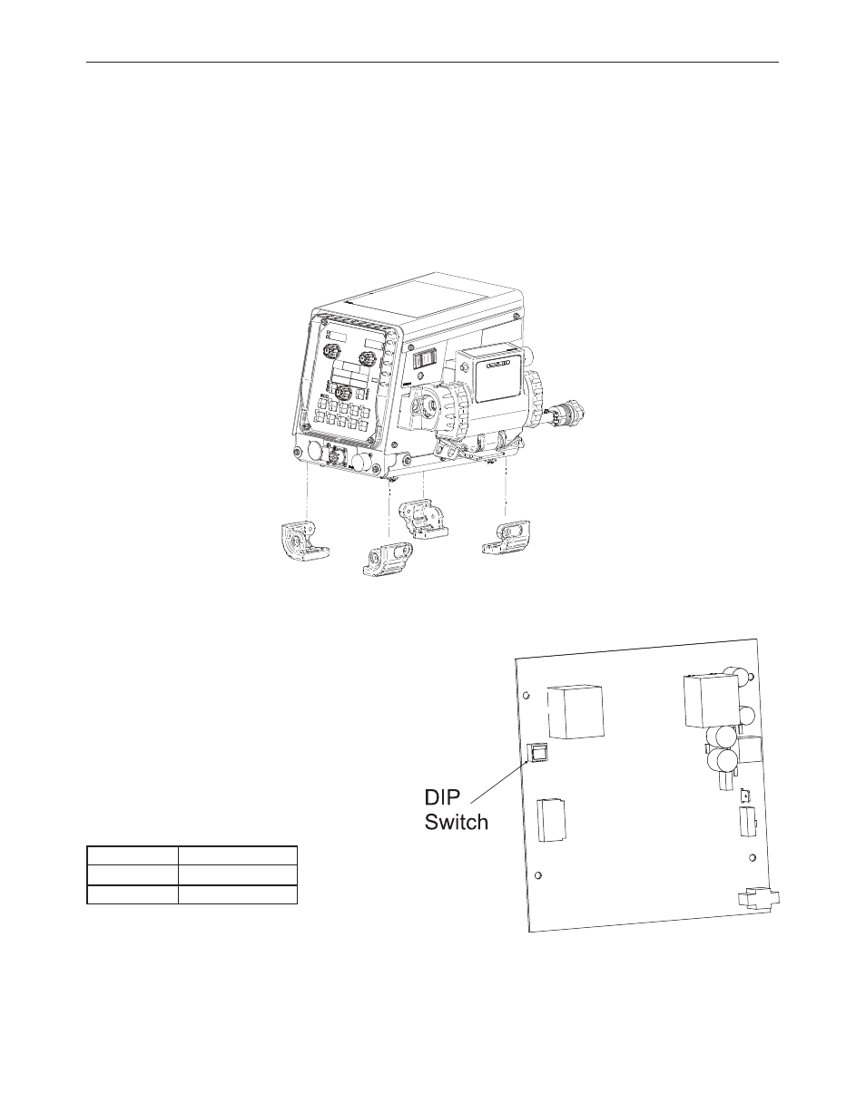
single/dual user inTerface conVersion
(See Figure A.4)
The Power Feed 84 uses the same user interface for
both single and dual models. A DIP switch on the back
side of the user interface board sets the board configu-
ration.
1. Turn power OFF at the welding power source.
2. Remove the (4) screws securing the user interface.
3. Set the DIP switch on the back side of the user inter-
face per the table.
configuration
dip switch setting
Single
On
Dual
Off
4. Reassemble the user interface.
FIGURE A.3
FIGURE A.4