Control box, Gas flow sensor – Lincoln Electric IM10178 POWER FEED 84 U.I. CONTROL BOX User Manual
Page 15
A-8
INSTALLATION
POWER FEED 84, POWER FEED 84 DUAL
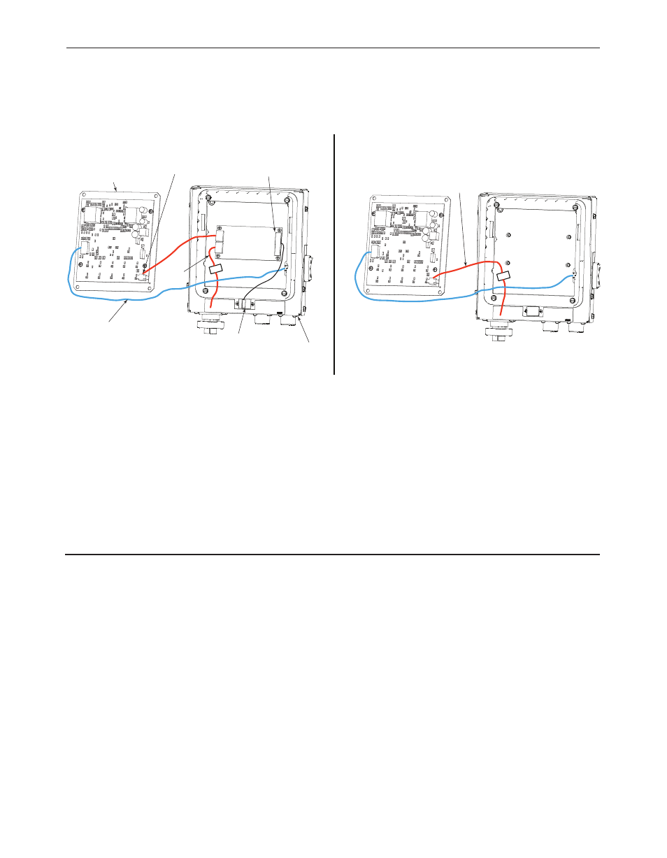
control box
(See Figure A-7)
5. If the control box will have USB installed:
a. Install the USB board into the control box, oriented
with the 10 pin connector on the right-hand side.
b. Assemble the USB port to the case front. Connect
the harness to the USB board.
c. Connect one of the USB jumper harnesses to the
control box harness. Connect the other to the 4 pin
connector on the back of the User Interface.
6. Connect the Cold Feed/Gas Purge harness to the back
side of the user interface.
7. Connect the User Interface to the harness as shown.
8. Secure the User Interface to the Control box with (4)
screws.
gas flow sensor
The gas flow sensor uses a mass flow sensor for
measuring gas flow in the range of 0 – 105 cfh (0 – 50
l/min).
The gas flow sensor kit is compatible with the following
gases:
• Air
• Argon
• CO2
• Helium
• 98Ar 2CO2
• 90Ar 10CO2
• 85Ar 15CO2
• 80Ar 20CO2
• 75A5 25CO2
• 90He 7.5Ar 2.5CO2
• 55He 42.5Ar 2.5CO2
• 98Ar 2O2
• 98Ar 2N2
Dual feeders require (2) gas flow sensors.
With USB
User Interface
Control Box
USB port
Jumper
Harness
10 pin connector
right hand side
4 pin connector
User Interface
Cold Feed/Gas Purge Harness
Without USB
Connect the
harness directly
to the board.
Figure a.7