Details of input and output signal – IAI America RCM-GW-CC User Manual
Page 60
56
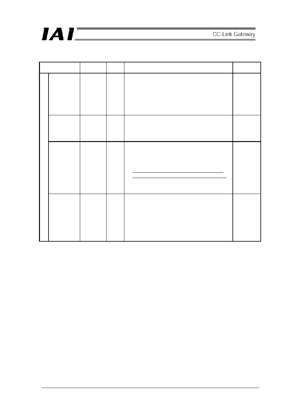
Details of input and output signal
Signal type
Application
Signal
name
Contents Detail
Position data
designation
24bit data
-
24 bit integer with sign (unit: 0.01mm)
Set position data in hexadecimal number of 24 bits.
Example) In the case of +25.4mm, designate
0009EC
H
(decimal 2540).
(Note)
●
When the integer is negative, it is indicated by
complement of 2, therefore, the uppermost bit
becomes “1.”
Current limit
value
8bit data
-
Set current limit value when push to set push force
in hexadecimal number. (unit%)
Setting range is from 00
H
to FF
H
, and FF
H
=100%.
Example) When setting to 50%, set it as
FF
H
50%=255×50%=127(decimal)=7F
H
.
Speed
designation
24bit data
-
24 bit integer (unit 0.01mm/sec)
Set command speed in hexadecimal number.
Example) In the case of 200mm/sec, the data is
0004E20
H
(decimal 20000).
(Note)
●
When speed is not set, or setting is “0,” or the
setting is “0,” stop is kept. Alarm does not occur.
When changing the speed by changing the
setting to “0” during movement, it decelerates and
stops.
PLC input
Acceleration
and
deceleration
8bit data
-
Set acceleration and deceleration in hexadecimal
number.
(Unit: 0.01G)
Example) When setting to 0.2G, it is 14
H
. It is C8
H
(decimal 200) at maximum 2G.
(Note)
●
When acceleration and deceleration are not set,
note that setting of parameter No.9 “Acceleration
and deceleration initial value” is not applied.