2 actuator operating pattern, 3 various settings on sio link side – IAI America RCM-GW-CC User Manual
Page 103
99
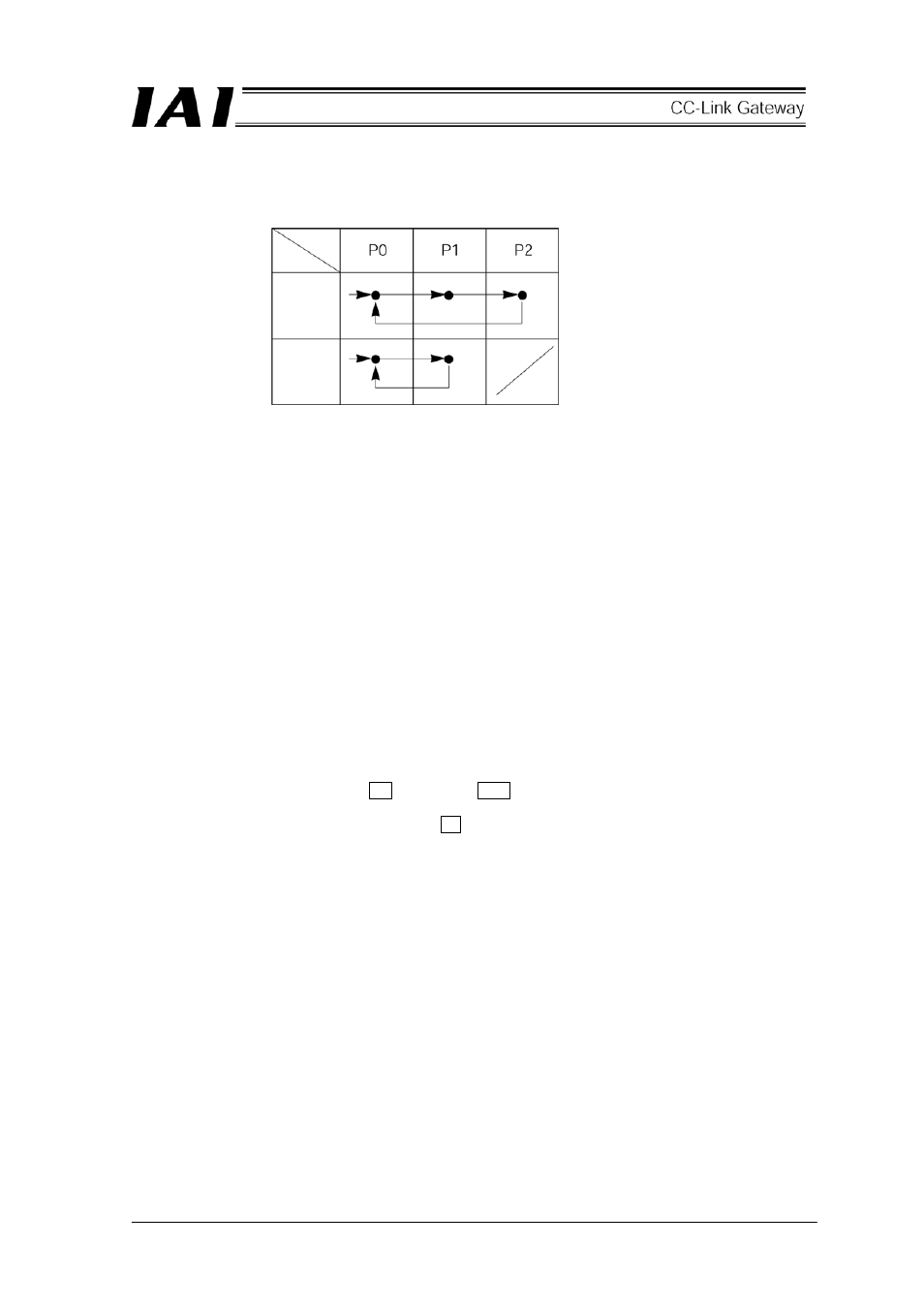
9.2 Actuator operating pattern
Prepare position tables for all of the three axes, and designate position No. from the PLC to operate.
9.3 Various settings on SIO link side
(1) Setting of SIO link
[1] Connect personal computer (supporting software) or teaching box to the gateway unit and turn ON the
port switch.
(Note) Perform SIO link only on axis to be set. In other words, connect only axis to be set to the
four-way junction. Connect and disconnect the connector sequentially for every setting.
[2] Start the personal computer supporting software.
[3] Click the “Set (S)” → “Controller setting.”
[4] Click the “Axis No. assignment (N).”
[5] Axis No. assignment table appears, then set No.
[6] Click the “OK,” then “ESC.”
[7] Connect and disconnect the SIO link cable to set the next axis No.
[8] When ended, finally connect all axes to the SIO link.
(2) Setting of SIO communication speed
Set parameters for the SIO communication speed subsequently from the status of (1).
[1] Restart the personal computer supporting software, then SIO link axis information (0 and 1 at this
time), and confirm them.
[2] Click the “Parameter (P)” → “Edit (E).”
[3] Select the axis 0 → click the > → click the OK .
[4] Parameter screen appears, then set the No. 16 SIO communication speed to 230400 (230.4kbps),
transmit it to the controller and close with × .
[5] Select the axis 1 at [2] to [4] to execute.
Position
Axis
First axis
Second
axis
Third axis