IAI America RCM-GW-CC User Manual
Page 49
45
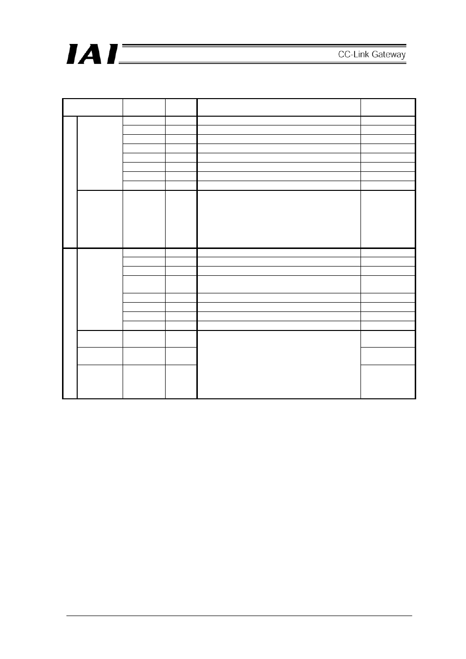
Details of input and output signal
Signal type
Application
Signal
name
Contents Detail
F/7
-
Cannot be used.
-
E/6
-
Cannot be used.
-
D/5
-
Cannot be used.
-
C/4
SON
Servo on command
B/3 STP
Pause
command
A/2
HOME Home return command
9/1 CSTR
Start
command
Position
data
designation
8/0 RES
Reset
command
PLC output
Position
data
designation
16 bit data
-
Set command position No. in hexadecimal
number.
Example)
Perform setting for two axes on higher byte
and lower byte. When the higher byte axis
is position No. 15 and lower byte axis is
position No.33, the setting is Hex0F21.
F/7
EMGS On emergency stop
E/6
-
Cannot be used.
-
D/5
PWR
Controller preparation completion
C/4 SV
Operation preparation completion (Servo on
status)
B/3 MOVE
On
moving
A/2
HEND Home return completion
9/1 PEND
Positioning
completion
Status
signal
8/0 ALM
Alarm
occurring
Zone signal
output 2
b15/b17 ZONE2
Zone signal
output 1
b14/b6 ZONE1
PLC input
Completed
position No.
(Alarm
output)
6 bit data
(b13-8/b5-
0)
PM32
–
PM1
Outputs completed position No. and status of
zone signal in hexadecimal number. Read the
completed position No. in binary value of 6 bits.
And, alarm content is outputted to the completed
position No. while an alarm occurring (ALM signal
is ON).
(For alarm content to be outputted, refer to the
“List of alarm content” in the next table.)