IAI America RCM-GW-CC User Manual
Page 15
11
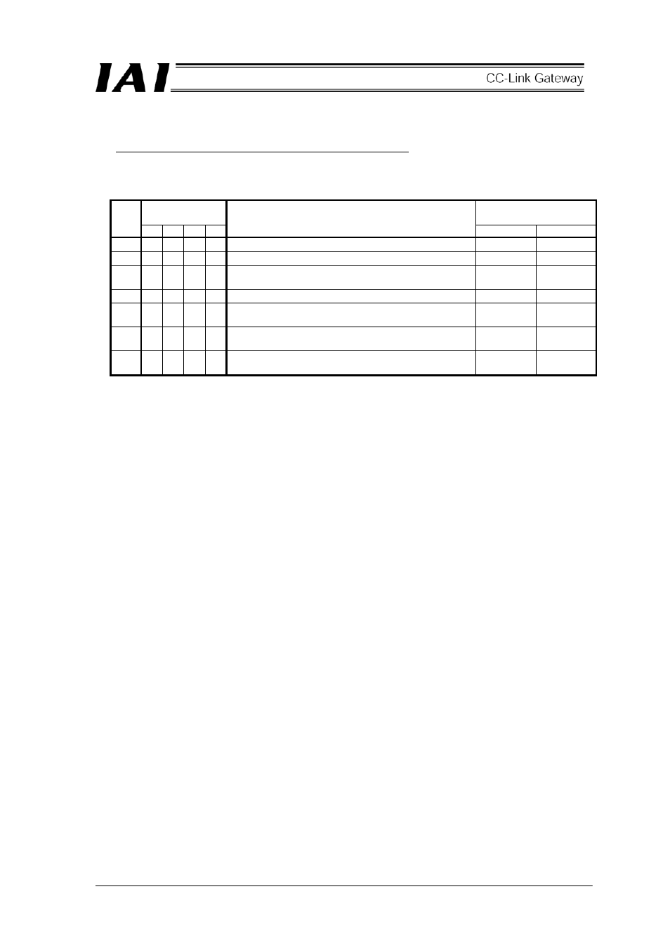
[3] Mode setting switch
This switch sets the operation mode of the CC-Link gateway.
Turn off the power for the CC-Link gateway to operate this switch.
When selecting No.1, No.3 and No.4, setting of the position table for the controller is disabled.
SW1
Input and output byte
number
No.
4 3 2
1
Description
Output Input
1
Ч
Ч Ч Ч Position data limit designating mode
46 46
2
Ч
Ч ○ Ч Position No. designating mode
46 46
3
Ч
○ Ч Ч Position/speed/acceleration and deceleration
designating mode
46 46
4
Ч
○ ○ Ч Push operation enable mode
46 46
5
Ч
Ч Ч ○ Simple direct value/Position No. designating mode
Large
176 176
6
Ч
Ч
○
Simple direct value/Position No. designating mode
Middle
136 136
7
○
Ч Ч ○ Simple direct value/Position No. designating mode
Small
68 68
[4] External port switching input
Connector port for teaching box and personal computer can be switched ON/OFF by external signal
(no-voltage contact).
When the port switch [9] for the CC-Link gateway main body is OFF, this input is enabled, and when the
input signal is ON, the port is turned ON. (Refer to the [9] port switch.)
[5] Controller communication line
This is a wiring connecting terminal for the communication line of the SIO communication (Modbus)
connector.
[6] CC-Link communication connector
This is a wiring connecting terminal for the CC-Link communication.