IAI America RCM-GW-CC User Manual
Page 28
24
a.
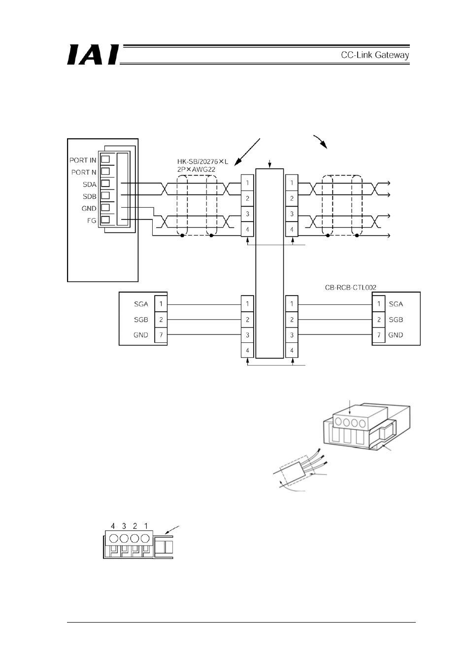
Detail Connection Diagram
The diagram below shows the details of the SIO communication connection. The controller link cables
are optionally prepared, but the communication main line must be prepared by the customer.
b.
Preparation of Communication Main Line
[1] Strip off approx. 15-20mm of the sheath
from the two-paired shielded cable.
[2] Install the cable protective tube.
[3] Insert three cables into the cable insertion
hole of the connector without stripping off
the envelope of the conductors.
[4] Pressure-weld the cable press-fit housing
with the cables inserted from above.
[5] Heat-treat the cable protective tube.
Pin numbers of e-CON connector
Be sure to insert the terminal resistor (220
Ω, 1/4W) into the end of the communication main line.
(between No. 1 and No. 2 of the e-CON connector)
Gateway unit
Two-paired shielded cable
Recommended brand:
Taiyo Electric Wire & Cable
SIO
communication
main line
Four-way junction (AMP: 5-1473574-4)
e-CON connector (AMP: 4-1473562-4)
Housing color: Green
Controller link cable
Yellow
Orange
Blue
Controller 1
Controller 2
Yellow
Orange
Blue
e-CON connector (AMP: 3-1473562-4)
Housing color: Orange
Press wielding
Locking tab
Cable tube
Two-paired shielded cable
Locking tab
e-CON connector