5 commissioning – Fairbanks X SERIES PR 5220 ETHERNET TRANSMITTER User Manual
Page 27
Section 5: Commissioning
05/11 28
51209 Revision 2
5 Commissioning
The meaning of indicator LEDs and the operating concept are described in Chapter 4.
5.1 Data Backup/Power Failure
The calibration data and parameters as well as all configuration and interface data are stored in a
non-volatile (EAROM) memory. Unauthorized data changing can be prevented by an access code.
Additional write protection is provided for calibration data and parameters (CAL switch, see
Chapter 5.1.1).
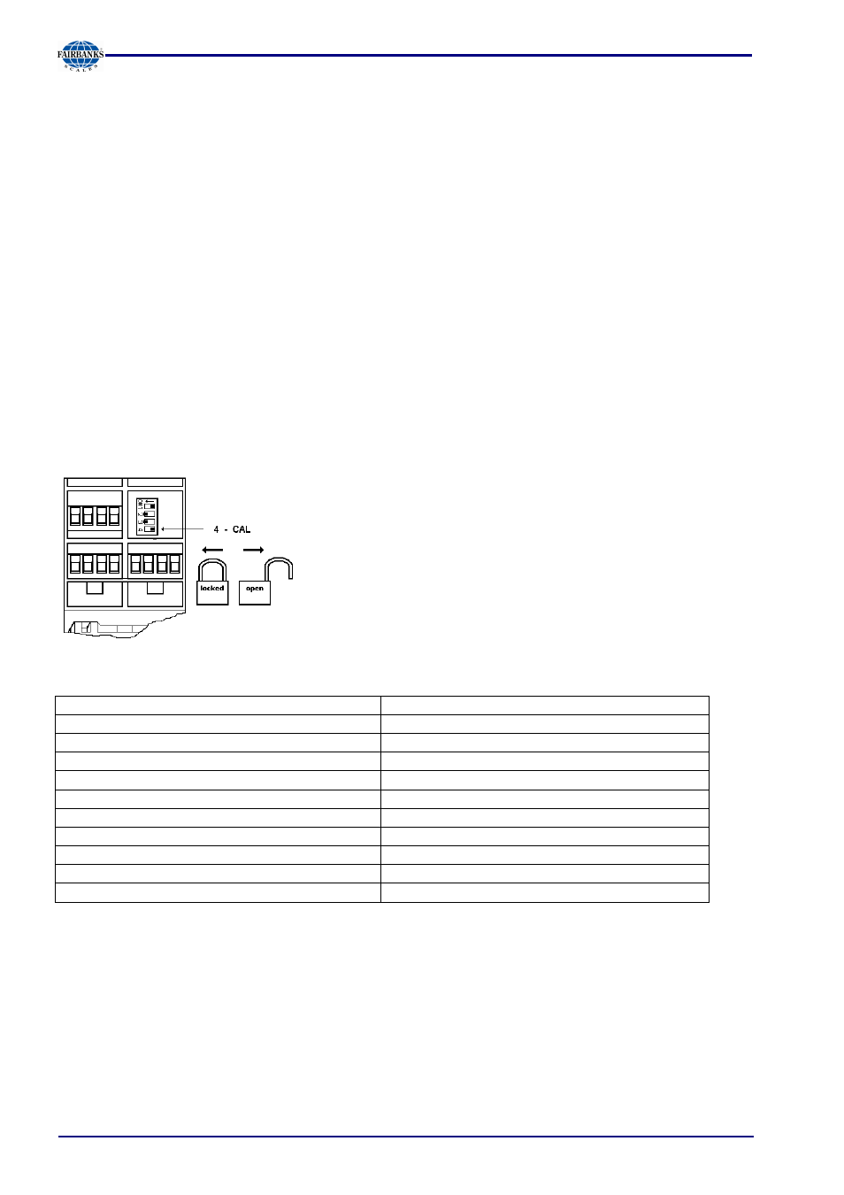
5.1.1
CAL Switch
The CAL switch protects the calibration data / parameters against unauthorized access.
When the CAL switch is in 'open' position, the calibration data and parameters can be changed
using the PC program or via the Profibus connection.
With the CAL switch in the 'closed' position, the calibration data (e.g. dead load, Span) and
Parameters (e.g. measure time, zero tracking etc.) cannot be changed.
The CAL switch is located under a cover that can be opened by
means of a knife.
For ’legal-for-trade’ applications, set the CAL switch (4) to the
left position and seal the cover.
5.1.2
Factory Settings
Calibration data
Calibration data
Full scale (Max) <3000>
Measure time (M) <320>ms
Scale interval <1>
Measuring rate <160>ms
Dead load <0.000000>mV/V
Standstill time <1>M
Span <1.000000>mV/V
Standstill range <1.00>d
Tare timeout <8>M
Calibration parameters
Overload (range above Max) <9>d
Zero-setting range <50.00>d
* W & M mode
Zero-tracking range <0.25>d
Filter
Zero-tracking step <0.25>d
Frequency <1.56 Hz>
Zerotrack repeat <0>M
* Parameter W&M must be set to 'on' or 'off' prior to input of the calibration data, see Chapter
5.4.20.
.