Process alarm display block events, 5 process alarm display block events – Micromod MOD: 30ML Functions Data Base Reference User Manual
Page 70
MOD 30ML Functions
PROCESS ALARM DISPLAY BLOCK
2.6.4
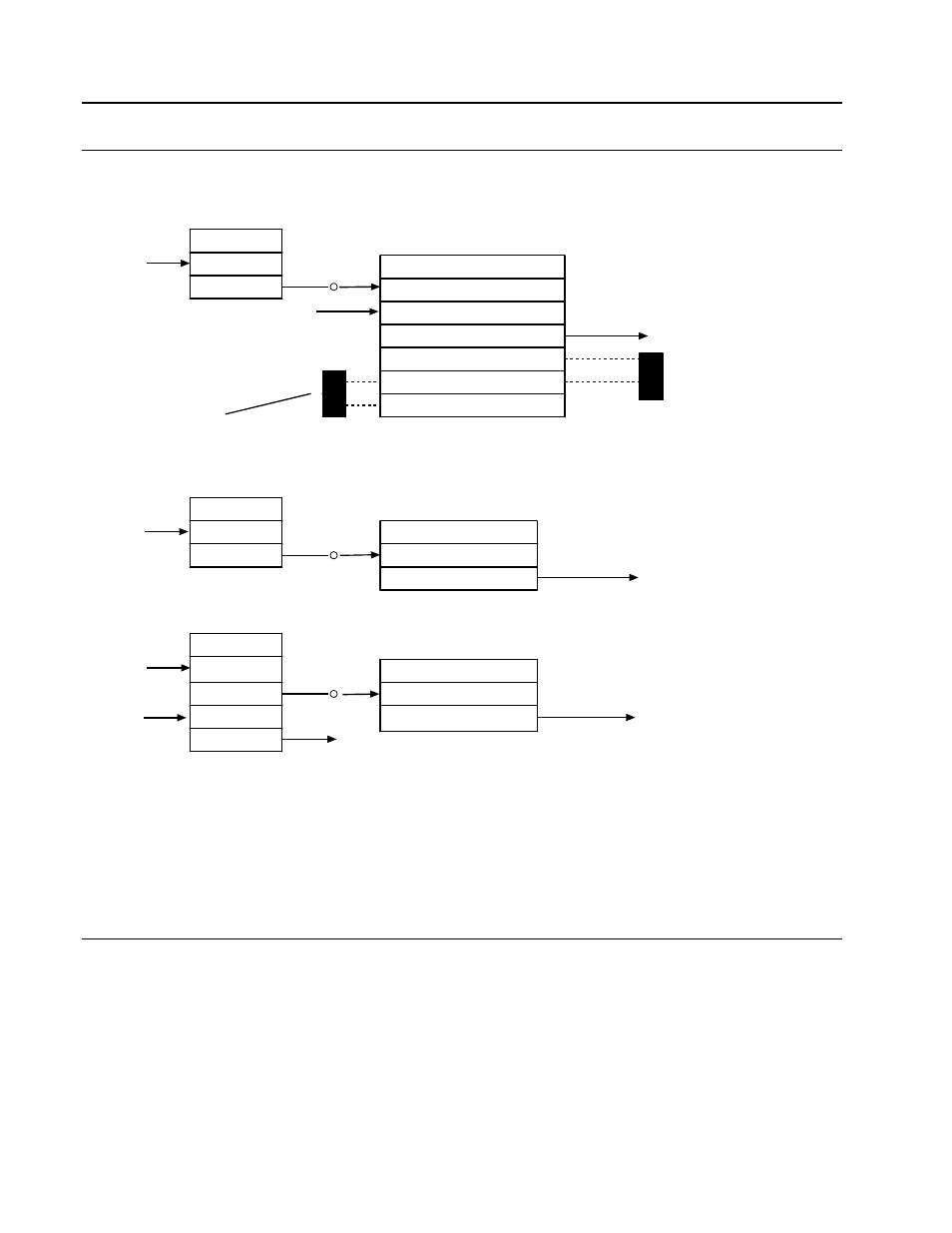
Typical Block Connections for Process Alarm Display Block
Typical softwiring connections are shown in Figure 2-23.
HLSTAT
R
VCI1
VCIM1
Result
A
PAD2
Alarm Input
Alarm Active
Discrete Output to Another
Function Block
R
DI1
DIM1
Result
EXAMPLE 2 Alarm on a Discrete Process Input
EXAMPLE 1 Alarm on a Floating Point Process Variable
EXAMPLE 3 Alarm on a State Variable
A
PAD3
Alarm Input
Alarm Active
Discrete Output to Another
Function Block
STATE
TM1
Timer Disable
State
Timer Reset
High Limit
TRIPVAL
U
A
PAD1
Acknowledge Input
Alarm Input
Alarm Active
Discrete output to another
function block
Operator indication
of acknowledgement
and trip value
(through CL block)
Logical Source Pointer from another
function block
Unacknowledged
Trip Value
Operator write access to trip
value, and control reporting
Report
Figure 2-24. Process Alarm Display, Typical Block Connections
Acknowledge Input (ACKINP)
The acknowledge input is edge triggered so that a value of 0 (FALSE) followed by a value of
1 (TRUE) acknowledges the alarm. If a discrete variable is connected, it is used to
acknowledge an alarm and reset the input. If no alarm acknowledgement input is connected,
the alarm can still be acknowledged in other ways as described in Process Alarm Operation.
2.6.5
Process Alarm Display Block Events
The event codes (and their suggested text messages) for the process alarm display block are
given below. See the descriptions of data base attribute #02 for additional information. See
the system event block for event transitions.
0
BLOCK STATE SET TO RUN
1
BLOCK STATE SET TO HOLD
2
BLOCK STATE SET TO OFF
3
BLOCK STATE SET TO DEBUG
4
text is user defined
2-62