Process alarm display block (pad), 6 process alarm display block (pad) – Micromod MOD: 30ML Functions Data Base Reference User Manual
Page 57
MOD 30ML Functions
PROCESS ALARM DISPLAY BLOCK
2.6
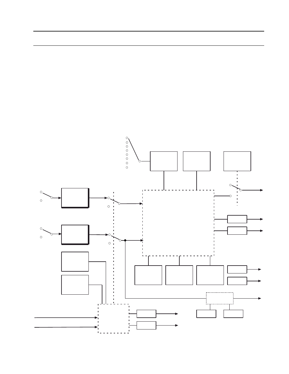
PROCESS ALARM DISPLAY BLOCK (PAD)
The process alarm block is used to initiate a discrete alarm signal to advise the operator of
an irregular process condition. The alarm is calculated by comparing an alarm source with a
trip value. The alarm source (input) is usually a value in some other block that the operator
wishes to monitor. The type of comparison made is specified by the trip condition. Depending
on the result of the comparison, the alarm is considered active or clear (inactive).
The alarm source value is shown on line 6 of the front panel display. The source value can
also be indicated on a bar display that includes an intensified segment identifying the trip
point.
This block has two discrete outputs that indicate whether the alarm is active or
acknowledged. These outputs can be used to initiate logic in other blocks throughout the
database. The user can acknowledge the existence of an alarm by any one of several
methods as described in Section 2.6.1. A functional block diagram of the block is shown in
Figure 2-19.
Alarm Input LSP Quality
Acknowledge Input LSP Quality
YES
Process Alarm Calculation
(See example diagram)
Trip Condition
Hysteresis
(Floating Point
Alarm)
* Data Type may be?
Count, Discrete, Short State,
Long State, Floating Point,
Msec Time, or Date
NO
Report Events
Trip Value *
Priority
(0 to 255)
Less
Less or Equal
Greater
Greater or Equal
Equal
Not Equal
Deviation
Suppress
Calculation
(YES, NO)
Quality Check
AQ
UQ
U
A
Scaling
HRNG
LRNG
TAG1
TAG2
GOOD
BAD
NONE
Discrete
LSP
LSP *
Value
Alarm Input
GOOD
BAD
Bad Inputs
Accepted
(YES, NO)
State
(RUN, HOLD,
OFF, DEBUG))
Acknowledge
Input
Figure 2-19. Functional Block Diagram, Process Alarm Display Block
2-49