Igure, Ormal operation indication, Ain screen results – MaxPower Corp Gamatronic Power+ RM100 User Manual
Page 74: Power+ start-up is now complete
Gamatronic Electronic Industries Ltd.
58
POWER+ RM100,
3
X
208
V, User Guide, Release 2.7ys
If the display continues to indicate BYP, check on the Static Switch panel, that the inverter is
running.
If the inverter indicator on the Static Switch panel is OFF:
● Press the Inv/Byp button on the static switch panel to switch the inverter ON and
wait for the indicator to light.
● Press the Inv/Byp button on the lower right of the control panel.
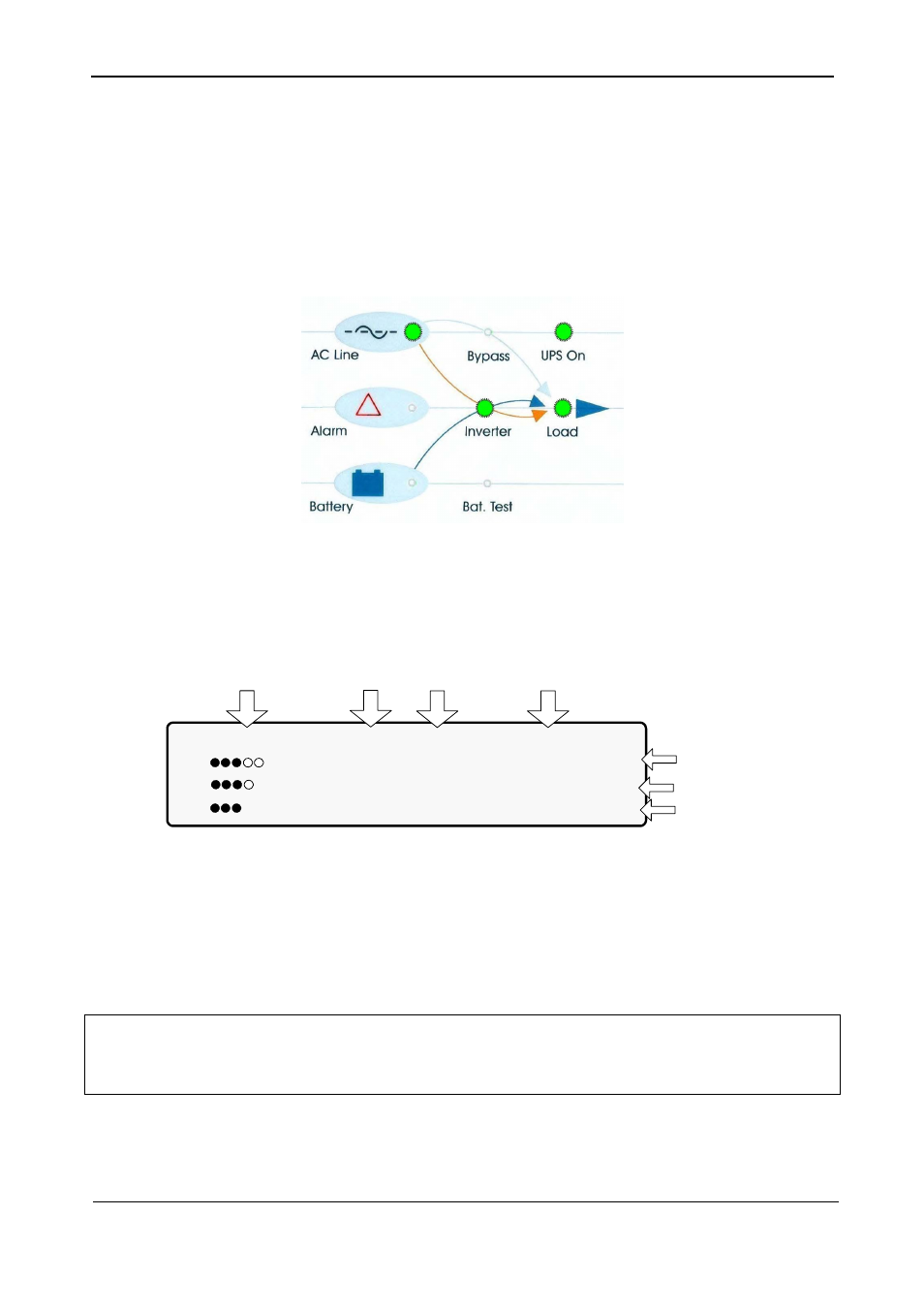
Figure 68: Normal operation indication
2.
Connect the load and observe the results on the display.
LOAD LEVEL ---11:20:25---
L1: _____ 030A, 120V BATTERY: 432V
L2: ______ 024A, 120V UPS OK (ON)
L3: _______ 022A, 120V STSW OK (INV)
Load level
bar graph
Output
current
Output
voltage
Current
time
Battery
voltage
Status
indications
Figure 69: Main screen results
3.
Observe that the “dot” bar graph now indicates the load presence and relative power
consumption. The number of black dots represents kW, and the number of black and
white dots together represents apparent power in kVA.
POWER+ start-up is now complete.