3 bypass operation (automatic), 4 bypass operation (manual), Bypass operation (automatic) – MaxPower Corp Gamatronic Power+ RM100 User Manual
Page 36: Bypass operation (manual), Igure, Power failure indication, Ypass mode, Ed alarm flashing
Gamatronic Electronic Industries Ltd.
20
POWER+ RM100,
3
X
208
V, User Guide, Release 2.7ys
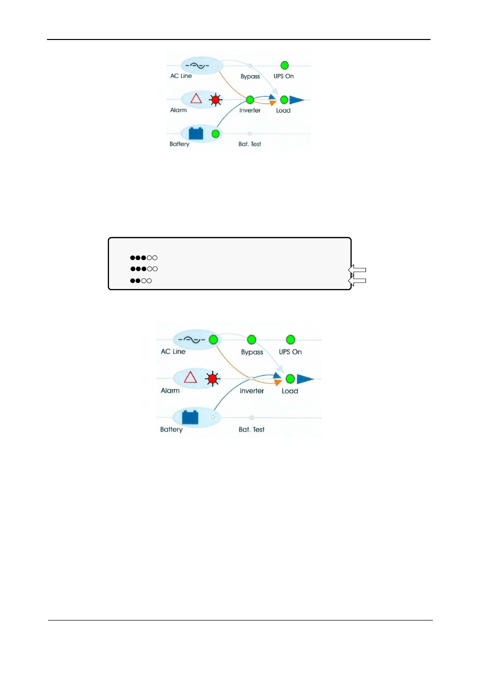
Figure 16: AC power failure indication
4.9.3
Bypass Operation (Automatic)
During Bypass operation, the ac feeds the load via the bypass static switch. The red alarm
flashes to indicate abnormal status.
LOAD LEVEL ---12:01:11---
L1: _____ 030A, 120V BATTERY: 432V
L2: _____ 029A, 120V UPS OK (ON)
L3: ______ 022A, 120V STSW OK (BYP)
Status
indications
Figure 17: UPS in Bypass mode
Figure 18: Red alarm flashing
4.9.4
Bypass Operation (Manual)
If the Power+ is manually switched to bypass operation by pressing the Inv/Byp button, the load
is transferred to the mains ac input line. Transfer back to normal operation must be performed
manually. The red alarm indicator flashes (Figure 18).