Installation and basic functionality, Plug-in modules – GF Signet 8900 Multi-Parameter Controller User Manual
Page 6
6
Signet 8900 Multi-Parameter
3. Installation and Basic Functionality
This section lists all items included with individual 8900 system components, describes installation detail for plug-in modules and base
units, and provides information and instruction on the basic functionality of the plug-in modules.
3.1 Unpacking
Base units, plug-in modules, accessories and spare parts are sold, packaged and shipped separately from the factory. Unpack all
components carefully. The following items accompany every 8900 base unit:
•
8900 Base Unit with a backlit LCD
•
Front Face Panel Gasket (pre-installed on base unit)
•
Quick-clip panel mounting bracket
•
Adhesive Template for panel cutout
•
Instruction Manual, Paper copy – English
•
CD-ROM containing instruction manuals in English, French, German, Spanish, Italian and Portuguese
3.2 Tools and Equipment Required:
•
Philips screwdriver (medium tip)
•
Standard screwdriver (small/medium tip)
•
Diagonal cutters (small)
• File
(fi ne)
•
¼-DIN punch or jigsaw suitable for cutting panel opening to within 1 mm (0.020 in.) tolerance.
•
Remove terminals from the receptacle of each plug-in module prior to installation.
•
Use diagonal cutters to remove slot shields from the rear panel for optional plug-in modules as required.
Only remove shields for slots to be used (UL safety requirement).
•
Smooth any protruding edges with a fi le.
•
Reinstall the rear panel; it will hold the modules securely in place.
4. Plug-in
Modules
•
If the 8900 Base Unit will be mounted in a panel, plug-in modules may be installed either before or after the base unit is mounted.
If the 8900 Base Unit will be mounted using the accessory Wall Mount Bracket, fi rst install plug-in modules.
•
Plug-in modules are packaged in anti-static bags and contain individual instruction sheets and removable terminals for convenient
wiring. Minimize handling of plug-in modules to reduce the probability of damage due to static discharge.
•
Power Modules include adhesive labels to be applied to the outside of the 8900 enclosure in specifi c locations as illustrated in
section 4.2.
•
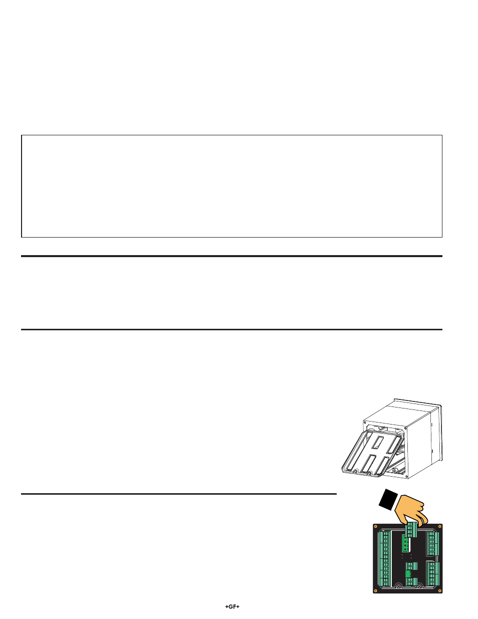
The rear panel of the 8900 must be removed prior to installing or removing plug-in modules.
If plug-in modules are already installed, the terminals must be removed prior to removing the rear
panel. It may be helpful to use a standard screwdriver to gently pry removable terminals away
from the receptacle on the plug-in modules.
•
Use a Philips screwdriver to loosen the two captive screws at the bottom of the panel. Pinch one
of the screws and swing the panel up approximately 90°, using the tab hinge at the top of the
panel, and pull it straight away from the base unit. Reverse this step to reinstall the panel after
the plug-in modules are installed.
Base unit
3-8900- _______ S/N___________________
I/O Module
3-8900.401-____ S/N___________________
Power Module 3-8900.402-____ S/N___________________
Relay Module 3-8900.403-____ S/N___________________
Relay Module 3-8900.403-____ S/N___________________
Ext Relay Module 3-8059-________S/N__________________
Output Module 3-8900.405-____ S/N___________________
OUT
2
OUT
1
SENSOR INPUTS
POWER
COMM POR
T/
OUT
4
OUT
3
RELA
4
RELA
3
RELA
2
RELA
1
UT 2 UT 1
PER
MM PRT
UT 4 UT 3
RE
2 RE
1
RE
4 RE
3
BL
RED
S LD
BL
RED
S L
S LD
BL
S L
S LD
-
-
ER IPUT
3
3
-
-
-
For future reference, for each installation, it is recommended to record the part number and serial number of each of the
components listed here:
Facility Tag Number or System ID (user assigned):_______________________