Sensor, Analog output 1 analog output 2, Sensor if two digital (s – GF Signet 8900 Multi-Parameter Controller User Manual
Page 15
15
Signet 8900 Multi-Parameter
3-8900.621C
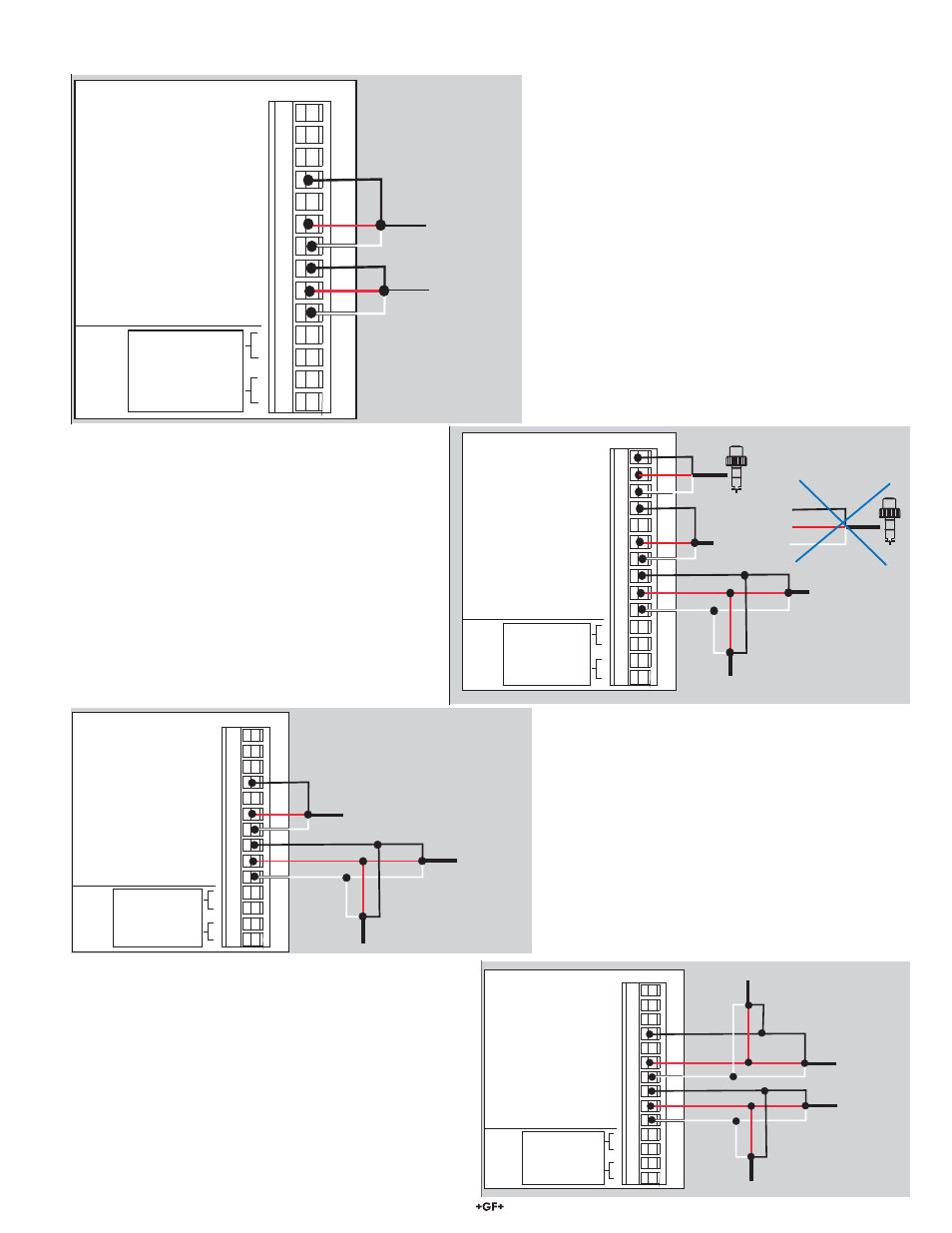
I/O Module 3-8900.401-X
1
2
3
4
5
6
7
8
9
10
11
12
13
14
+5VDC (Black)
Freq. Input (Red)
GND (Shield)
+5VDC (Black)
Freq. Input 2 (Red)
S L (Red)
GND (White/Shield)
+5VDC (Black)
S L (Red)
GND (White/Shield)
3
3
Analog Output 1
Analog Output 2
(if applicable)
(if applicable)
Frequency
Input
1
Frequency
Input 2
OR
S3L
Input
2
S3L
Input
1
+
-
+
-
S3L
Sensor
S3L
Sensor
S3L
Sensor
S3L
Sensor
3-8900.621C
I/O Module 3-8900.401-X
1
2
3
4
5
6
7
8
9
10
11
12
13
14
+5VDC (Black)
Freq. Input (Red)
GND (Shield)
+5VDC (Black)
Freq. Input 2 (Red)
S L (Red)
GND (White/Shield)
+5VDC (Black)
S L (Red)
GND (White/Shield)
3
3
Analog Output 1
Analog Output 2
(if applicable)
(if applicable)
Frequency
Input
1
Frequency
Input 2
OR
S3L
Input
2
S3L
Input
1
+
-
+
-
S3L
Sensor
S3L
Sensor
S3L
Sensor
If two digital (S
3
L) sensors are wired separately, the cable
length of each branch can be extended.
If terminals 4-6-7 are used for digital (S
3
L), the 8900
cannot accomodate two frequency inputs.
6.2.2
Digital Cable Routing Diagrams
To add a digital sensor to the digital (S
3
L) bus, connect
the RED, BLACK and WHITE wires into the existing bus
at any point.
The new sensor is added to terminals 4-6-7 so the sensor
load is divided between the two branches of the bus